3OM-1343-008_w.pdf - 第311页
6-80 AKFEDT -ID Nozzle Recog 1.0 mm 2.0 mm Length Diffusion Plate Reference Plane for Nozzle Attachment Height for Recognition Fig. 3F71 Lighting Method Select one of the following options as a lighting method for the no…
6-79
AKFEDT-ID
Fdcl Mk Image
Select one of the following options to specify how (bright or dark) the
image of the nozzle end should be captured in the front lighting system.
DarkBright
Fig. 3F70
Note
The set parameter is required for nozzle masking in the front lighting
system.
Lighting Method
Specify which lighting method can be used for each nozzle.
Select one of the following options.
Back-Lighting :
This function is available only in the back lighting
recognition system.
Front-Lighting :
This function is available only in the front lighting
recognition system.
Back/Front :
This function is available in both back and front
lighting recognition systems.
Note
"Front-Lighting" must be selected for such a nozzle that the image of the
area other than the nozzle tip appears dark in the back lighting system.
"Back-Lighting" must be selected for such a nozzle that the image of the
area other than the nozzle tip appears bright in the front lighting system.
0601-002
3.2 Nozzle Data
6-80
AKFEDT-ID
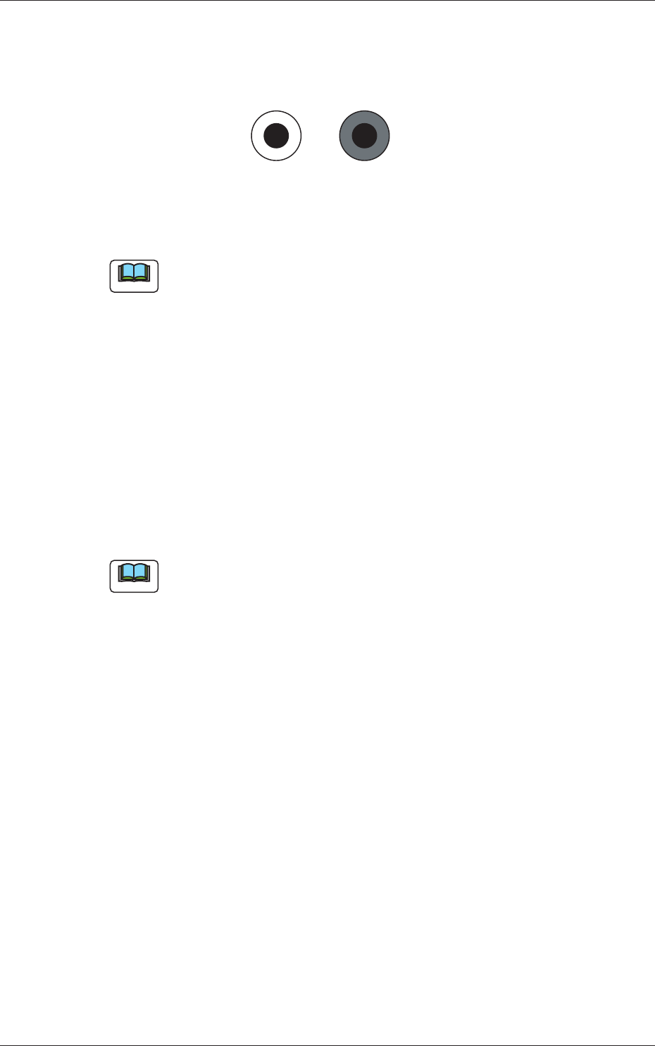
Nozzle Recog
1.0 mm
2.0 mm
Length
Diffusion
Plate
Reference Plane for
Nozzle Attachment
Height for
Recognition
Fig. 3F71
Lighting Method
Select one of the following options as a lighting method for the nozzle
recognition plane.
Back ltg, Fr ltg #1 (Ring Dn), Fr ltg #2 (Coax),
Fr ltg #3 (Ring Up)
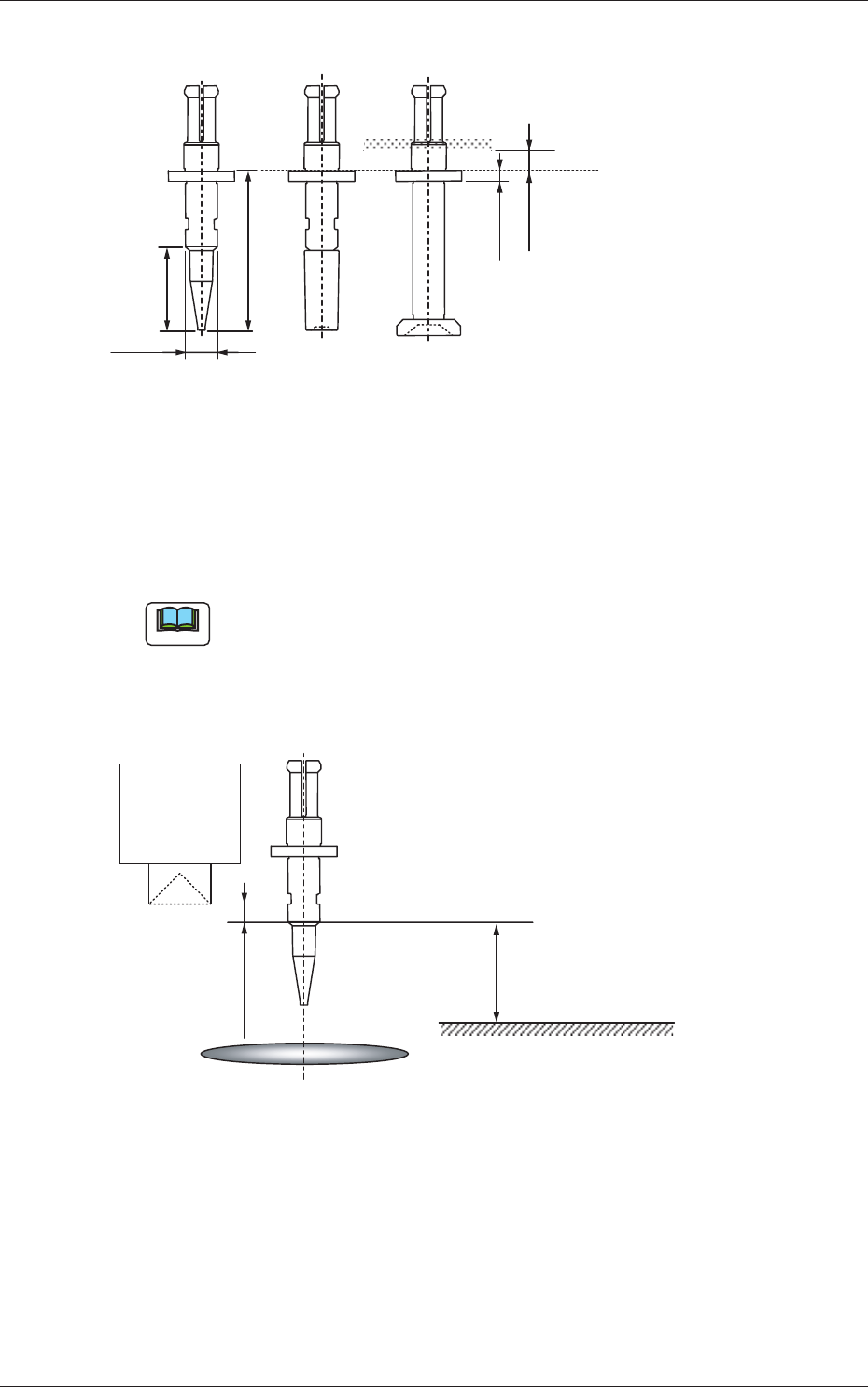
Note
The following condition is required for recognition of a nozzle.
•
The nozzle height direction should be the one as depicted in the fi gure
below.
•
The object nozzle for recognition should be arranged in the camera
sensor.
10.0 mm
PCB Surface
Linear
Measure
Sensor Light
Emitter
Component Recognition Camera Focus Position
1.0 mm or more
Camera Center
Fig. 3F72
Level [mm]
Set the height (level) of the nozzle recognition plane in comparison with the
nozzle end.
Outer Size [mm]
Set the outer diameter of the nozzle recognition plane.
0601-002
3.2 Nozzle Data
6-81
AKFEDT-ID
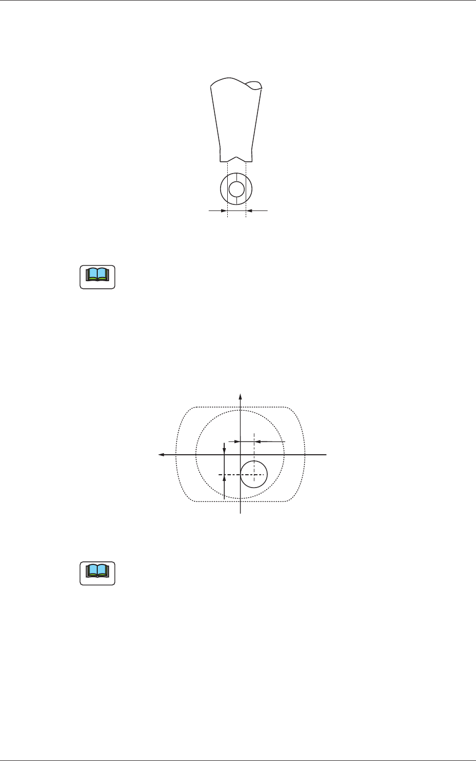
V-groove Size [mm]
When the V-grooved nozzle is used for cylindrical components, set the
size of the V-groove in the corresponding text box.
Fig. 3F73
Note
In the case of the nozzle without a V groove, set "0.00" in the
corresponding text box.
Eccntrc X (Horizontal), Y (Vertical) [mm]
When the center of the nozzle end is eccentric in comparison with the
outer shape of the nozzle, set the eccentricity in both X and Y directions
in the coordinate system viewed from the nozzle top side (clamp side).
-Y1
+X
+Y
-X1
Fig. 3F74
Note
Set "0.00" in both text boxes for standard nozzles.
0604-003
3.2 Nozzle Data