3OM-1343-008_w.pdf - 第122页
3-37 AKFEDT -ID (C01_06) Feeder Alternate Select "Enable" or "Disable" to determine whether or not the feeder alternate function should be used. Disable : The feeder alternate function is not used. En…

3-36
AKFEDT-ID
(C01_03)
C
Set control commands in the text boxes.
Notice
If a control command other than the following ones is used, the step
becomes invalid.
- (hyphen) :
This command handles the steps as those for the
placement feeder location data.
E :
This command shows the end of the placement
feeder location data.
The step where "E" is set is valid.
S :
This command invalidates the steps specifi ed as
placement feeder location data.
X :
This command invalidates the steps specifi ed as
placement feeder location data and shows the end
of the data.
(C01_04)
Comment
Set a comment for each Fdr No.
Up to 32 characters (alphanumerics and symbols) can be used.
Alphanumeric characters and symbols can be used.
Note
(a) The performance of the machine is not affected by these commands.
In other words, it has nothing to do with or without these comments.
(b) It is recommended to set helpful information on components related
to the feeder Nos. (Fdr No.).
(C01_05)
Feeder Fixed
Select "Enable" or "Disable" to determine whether or not the feeder
positions should be fi xed in place.
When "Enable" is selected, the feeder Nos. (Fdr No.) and the
component ID are not affected by any insert and delete operations of a
component.
Disable :
The feeder position is not fi xed.
Enable :
The feeder position is fi xed.
0601-002
1.4 Placement Feeder Location Data

3-37
AKFEDT-ID
(C01_06)
Feeder Alternate
Select "Enable" or "Disable" to determine whether or not the feeder
alternate function should be used.
Disable :
The feeder alternate function is not used.
Enable :
The feeder alternate function is used.
(C01_07)
Fdr No.
When "Enable" is selected for the feeder alternate function, set the
destination feeder No. (Fdr No.) of the feeder that will work in place of
the feeder where a component pickup error has occurred in succession.
(C01_08)
Component Library Comment
Shown are the comments that were entered in the component library
data.
(C01_09)
Dir [deg], Carrier Data Type, and Width [mm]
Shown are the values specifi ed in the component library data.
(C01_10)
Fd. Pitch [mm]
Shown are the feed pitches specifi ed in the component library data.
(C01_11)
Used Parts
Shown is the number of components to be used for one unit PCB.
0601-002
1.4 Placement Feeder Location Data
3-38
AKFEDT-ID
0601-002
1.5 Placement Data
1.5.1 (D01) Placement Data Un
(D01_01)
Selection of Placement Data Unit
Select one of the following tabs (placement data groups) in one pattern
program.
U01 : First Placement Data Group
U02 : Second Placement Data Group
↓
Un : Up to 99 placement data groups can be specifi ed.
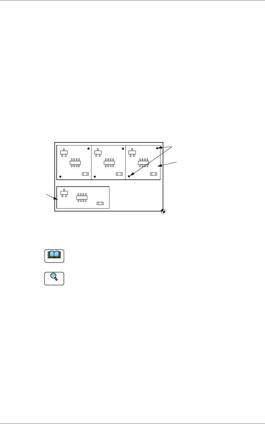
U02
U01
Placement Coordinate
Reference
Fiducial Marks
Fig. 3C28 Example of Placement Data
Note
(a) Use "U01" in normal cases.
(b) The operation and feeder location data are used commonly.
Reference
Refer to "3. Example of Pattern Program Creation" for details.
1.5 Placement Data