3OM-1343-008_w.pdf - 第94页
3-9 AKFEDT -ID (A01_06) PCB locate Sequence Select one of the following options as a PCB positioning sequence. Standard : Backup and Z Clamp Activated Mode #1 : Z Clamp Activated (A01_07) PCB transfer Sequence Select one…
3-8
AKFEDT-ID
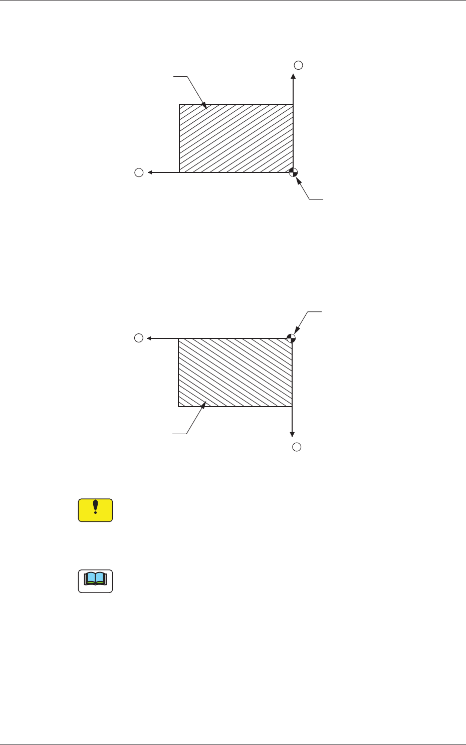
Front Right :
The placement coordinate reference is based on
the front right side and specifi ed as follows.
X +
Y +
PCB
Placement Coordinate
Reference (N
0)
Fig. 3C10
Rear Right :
The placement coordinate reference is based on
the rear right side and specifi ed as follows.
X
PCB
Placement Coordinate
Reference (N
0)
Y
+
+
Fig. 3C11
Notice
Be sure to set the same reference as the input and output
machines.
If a reference different from the input and output machines is
specifi ed, PCBs cannot be produced correctly.
Note
When a different reference is specifi ed in the pattern program and the
program is to be used for this machine, be sure to change the reference of
this machine to the different one.
0601-002
1.2 Operation Data

3-9
AKFEDT-ID
(A01_06)
PCB locate Sequence
Select one of the following options as a PCB positioning sequence.
Standard :
Backup and Z Clamp Activated
Mode #1 :
Z Clamp Activated
(A01_07)
PCB transfer Sequence
Select one of the following options as a PCB transfer sequence.
Synchronous Priority :
PCBs are received and transferred at the same
time.
Output Priority :
Priority is given to the PCB transfer after
component placement.
0601-002
1.2 Operation Data
3-10
AKFEDT-ID
0601-002
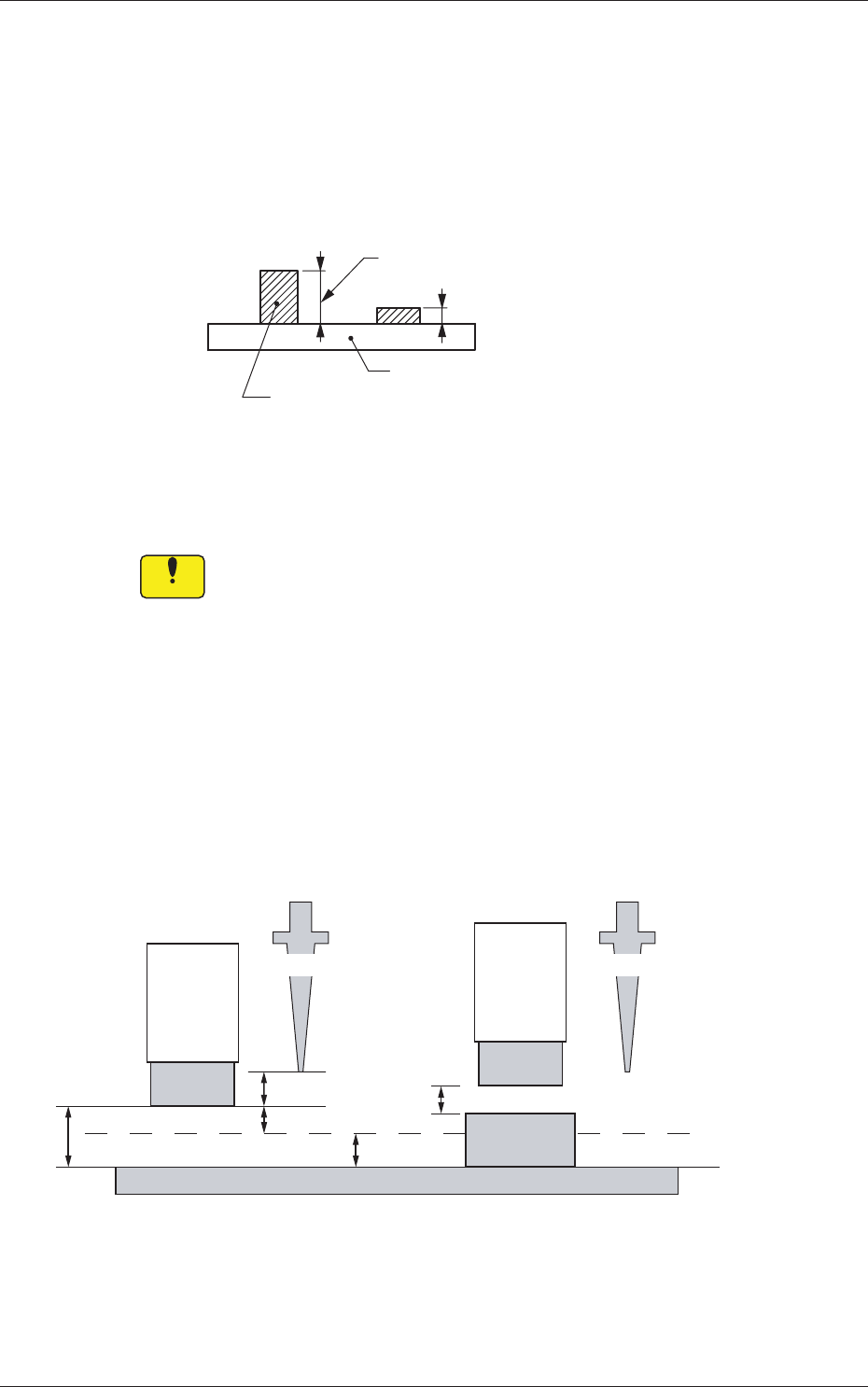
(A01_08)
Pre-Placed component thickness
Top [mm]
When some components are placed previously on a PCB by the input
machine, etc., and transferred to the main machine, be sure to enter the
thickness of the tallest component of all in the text box.
Tallest Previously-Placed Component
Set this thickness in the text box.
PCB
Fig. 3C12
•
Data Input Range
0 to 12.700
Notice
(a) When components are placed previously and the main machine
is operated with
"
0.00
"
in this text box, some of the previously-
placed components may interfere with components to be
placed newly.
(b) It is advisable that placement data should be created such that
shorter components are placed before the tallest one.
(c)
When the specifi ed thickness of a previously-placed
component differs from the actual one, the light emitter of the
linear measure sensor may interfere with the previously-placed
component.
3.0 mm
5.0 mm
2.0 mm
3.0 mm
2.0 mm
No Previously-Placed Component
Previously-Placed Component
NL Origin Position NL Origin Position
Light
Emitter
Light
Emitter
Previously-
Placed
Component
PCB
Placement Level
Fig. 3C13
1.2 Operation Data