3OM-1343-008_w.pdf - 第249页
6-18 AKFEDT -ID [3] Rectangular Angle X [deg] These parameters represent the amount of angular deviations (X directions) of the mark on the machine in comparison with the X directions in the machine reference coordinate …
6-17
AKFEDT-ID
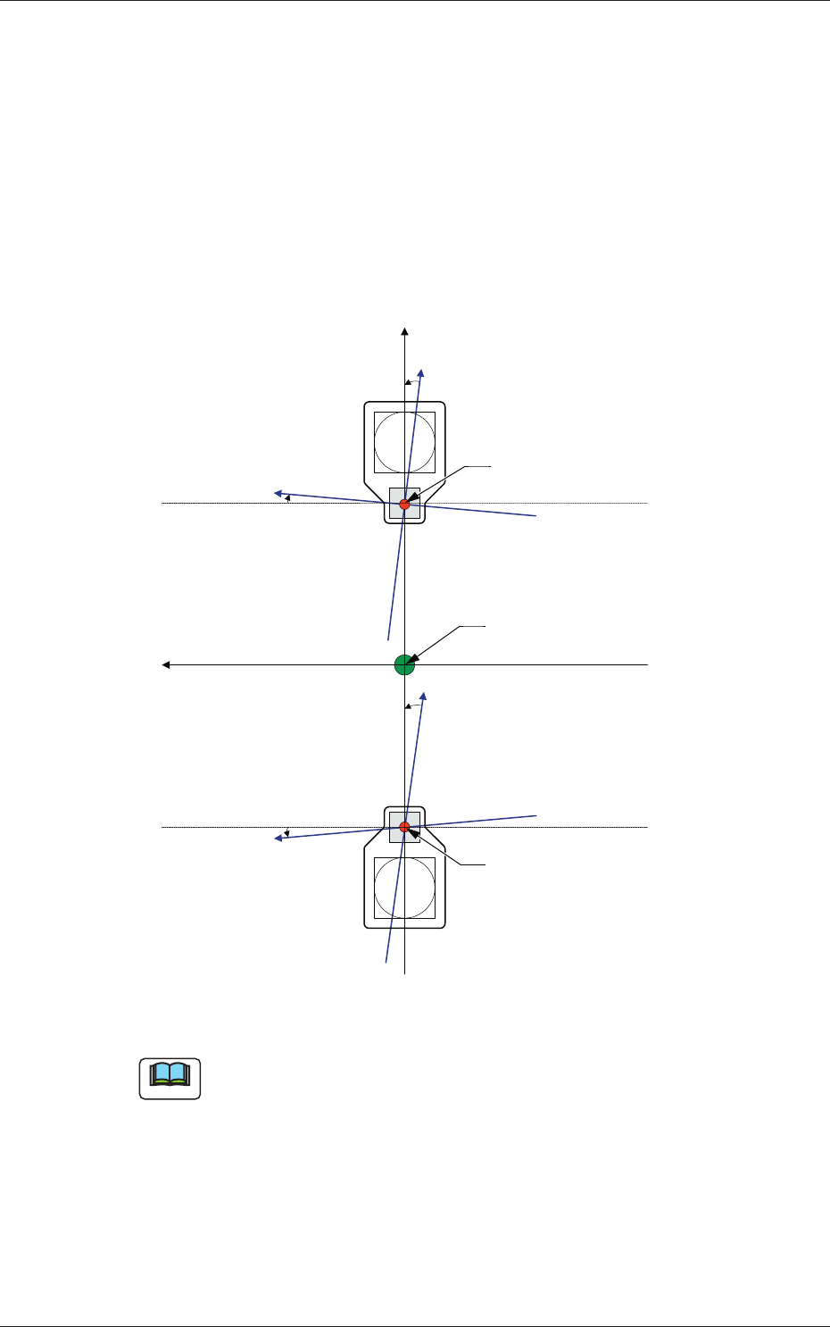
[1] X (Horizontal) and Y (Vertical) [mm]
The set parameters are used to adjust the positional deviation based on
the design dimensions representing the distance between the machine
reference coordinate origin and the center of the PEC recognition
camera at the head origin.
[2] Angle X and Angle Y [deg]
The set parameters are used to adjust the beam X and Y axes to the
machine reference coordinate system.
Xm (+)
Ym (+)
Yb (+)
Xb (+)
Yb (+)
Xb (+)
Xm-Ym : Machine Reference
Coordinate System
Xb-Yb : Real Beam Coordinate
System
Head Origin
Head Origin
Pm. Machine Reference
Coordinate Origin
Fig. 3F16
Note
A plus values must be entered in the "Angle X [deg]" and "Angle Y [deg]"
text boxes when the real beam coordinate system is tilted counterclockwise
(based on the machine reference coordinate system).
2.1 Device Offset Data
0601-002
6-18
AKFEDT-ID
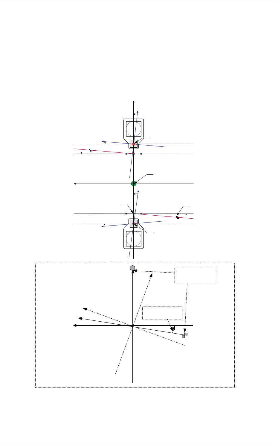
[3] Rectangular Angle X [deg]
These parameters represent the amount of angular deviations (X
directions) of the mark on the machine in comparison with the X
directions in the machine reference coordinate system.
The set parameters are used to check the three marks on the area of the
machine where only a little positional change can be made according to
temperature changes and adjust the beam X/Y axes such that they can
cross at right angles.
Xm (+)
Ym (+)
Yb (+)
Xb (+)
Yb (+)
Xb (+)
Xm'
Machine Reference
Coordinate System
Mark Coordinate
System
Beam Coordinate
System
Mark on Machine
Rectangular Angle
X [deg]
Head Origin
Head Origin
Pm. Machine Reference
Coordinate Origin
Standard Mark 2
Xm-Ym : Machine Reference
Coordinate System
Xb-Yb : Real Beam Coordinate
System
Standard Mark 1
Fig. 3F17
2.1 Device Offset Data
0601-002
6-19
AKFEDT-ID
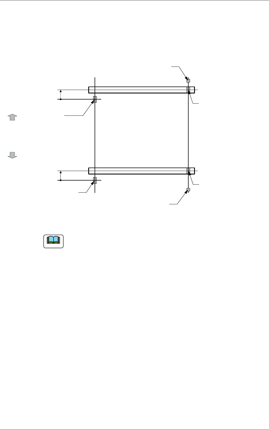
[4] Y-Axis Origin [mm]
The set parameters are used to maintain the beam condition (position)
set up right after the machine was assembled.
Use the values fed back automatically from the motion controller after
the Y-axis is zeroed (adjustment mode).
Master Side
Slave Side
Beam
Beam
Zeroing
Direction
Zeroing
Direction
Y-Axis Origin Offset
= (+) Value
Origin Mark
(Origin Signal Position)
Origin Mark
(Origin Signal Position)
Origin Mark
(Origin Signal Position)
Origin Mark
(Origin Signal Position)
Limit Sensor
Limit Sensor
Y-Axis Origin Offset
= (+) Value
Fig. 3F18
Note
(a) The displayed parameters cannot be edited manually.
(b) The Y-axis origin offset indicates where the origin signal position of
the master axis is located when viewed in the zeroing direction from
the origin signal position of the slave axis.
A plus sign will be affi xed when the origin signal position is located
in the same direction as the zeroing one. When it is located in the
opposite direction, a minus sign is affi xed.
2.1 Device Offset Data
0601-002