00198631-03_AI_Smart-Pin-Support_TX_DE_EN.pdf - 第52页
1 Introduction 1.3 Other instructions 52 Assembly Instructions / Montageanleitung SIPLACE TX V2 Series Smart Pin Support 07/2021 1.3.3.5 Dispatching ESD modules ► Always store modules and components in conductive packagi…
1 Introduction
1.3 Other instructions
Assembly Instructions / Montageanleitung SIPLACE TX V2 Series Smart Pin Support 07/2021 51
1.3.2 Use of original accessories and spare parts
Only use original spare parts and authorized accessories. The use of other parts will affect safety
and will invalidate the liability for any consequential damage.
1.3.3 ESD guidelines
1.3.3.1 What does ESD mean?
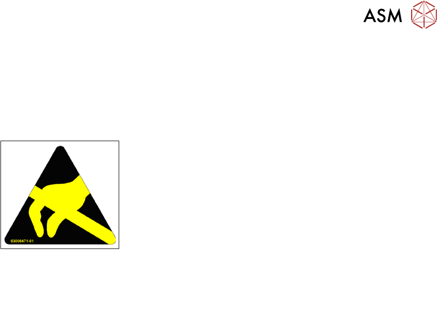
Fig.3: ESD label
Almost all of the modules in use today are equipped with highly integ-
rated Metal-Oxide-Semiconductor (MOS) blocks and components.
The manufacturing techniques used mean that these electronic com-
ponents are extremely sensitive to overvoltage and thus to electro-
static discharge.
The abbreviation for such modules is "ESD" (Electrostatic Sensitive
Device). "ESD" is used internationally. The following symbol on cab-
inet rating plates, racks or packaging indicates that components
which are sensitive to electrostatic discharge have been used and
thus that the modules concerned are also touch-sensitive.
ESDs can be destroyed by voltages and power levels that are far below the level that can be per-
ceived by humans. Such voltages occur if a person touches a component or module without
earthing themselves. Components that are exposed to such overvoltages do not generally appear
to be defective immediately - incorrect behavior starts after the component or module has been in
operation for some time.
1.3.3.2 Important measures to protect against static charging
► Most plastics can easily become charged and must therefore be kept away from at-risk com-
ponents.
► Always ensure that people, the workplace and packaging are safely earthed when handling
electrostatic sensitive components.
1.3.3.3 Handling ESD modules
As a general rule: Only touch electronic modules if you must carry out work on the modules. In that
case, make sure that you do not touch the pins or printed conductors when you pick up flat mod-
ules.
Only touch components if you are earthed by one of the following measures:
●
You are wearing an ESD wristband.
●
You are wearing ESD shoes.
●
You are wearing ESD shoe earthing strips on an ESD floor.
Immediately before you touch an electronic module, discharge your own body by touching a con-
ductive and earthed object (such as unpainted parts of a switch cabinet, a water pipe, etc.).
Do not allow modules with chargeable and highly insulating materials to touch one another, e.g.
plastic films, insulating table surfaces or items of clothing made from synthetic fibers.
Always place the modules on a conductive surface (table with an ESD coating, conductive ESD
foam, ESD bag or container).
Do not move the assemblies near to data view devices, monitors or television units. Keep a min-
imum distance of 10 cm to monitors.
1.3.3.4 Measurements and modifications to ESD modules
Only perform measurements on modules if one of the following conditions is fulfilled:
●
You are using an earthed measuring device (e.g. via PE conductors).
●
You are using a potential-free measuring device and discharge the measuring head before
the measurement (e.g.by touching an unpainted metal part of the controller casing).
► Always use an earthed soldering iron if you carry out any soldering work.
1 Introduction
1.3 Other instructions
52 Assembly Instructions / Montageanleitung SIPLACE TX V2 Series Smart Pin Support 07/2021
1.3.3.5 Dispatching ESD modules
► Always store modules and components in conductive packaging (e.g. metallized plastic bags
or metal sleeves) and dispatch them in conductive packaging
► If the packaging is not conductive, place the modules in a conductive envelope before pack-
aging. Use conductive expanded rubber, ESD bags, domestic aluminum foil or paper, for
example. NEVER use plastic bags or film.
► If the module has integral batteries, ensure that the conductive packaging does not touch or
short circuit the battery terminals and, if necessary, first cover the terminals with insulating
tape or material.
1.3.4 Validity of document
This document is valid for the following machine types:
●
SIPLACE TX V2-Series
The work described in this manual is divided into modules and is largely identical for all machine
types:
●
If the work required for specific machines differs from the standard procedure, this will be in-
dicated with reference to the machine number, series and delivery state.
●
Illustrations are only shown as examples. For example, the illustration of a specific machine
type or a machine with different paint finish does not imply that the information following the il-
lustration only applies to the shown machine type.
Please read the circuit diagram folder for any electrical checks.
●
Detailed circuit diagrams SIPLACE TX V2-Series [DE+EN: 00198460-xx]
1.3.5 Release history
Document
Smart Pin Support Option
SIPLACE TX V2-Series
Assembly Instructions
Edition Amendments
12/2018 Initial release
05/2019 Additional feature
●
New nozzle station added to scope of delivery
●
New section: "Convert nozzle station" (TI2018-12D02)
07/2021 Amendments and supplements:
●
Scope of delivery
●
New silicone hose
●
New connection cable
●
New nozzle magazines with 3 fiducials
●
Special features of SIPLACE Tray Unit
●
Conversion of nozzle station cancelled
●
Various editorial changes

1 Introduction
1.4 Abbreviations
Assembly Instructions / Montageanleitung SIPLACE TX V2 Series Smart Pin Support 07/2021 53
1.4 Abbreviations
Abbreviations Description
C&P Collect&Place
C&P20, CP20 Collect&Place head with 20 segments
CPP Collect&Pick&Place head
CPx Collective term for CPP, CP20, CP12 and/or CP6
ESD Electrostatic sensitive device
EMC Electromagnetic compatibility
P&P Pick&Place
NC Nozzle changer
SPS Smart Pin support
SC Station computer
TH TwinHead
ID Intermediate distributor