00198631-03_AI_Smart-Pin-Support_TX_DE_EN.pdf - 第60页
2 Brief Description 2.5 Required Working Time 60 Assembly Instructions / Montageanleitung SIPLACE TX V2 Series Smart Pin Support 07/2021
2 Brief Description
2.4 Tools and Equipment Required
Assembly Instructions / Montageanleitung SIPLACE TX V2 Series Smart Pin Support 07/2021 59
2.3.1 Parts required for the SPS option in SIPLACE TX V2 machines with SIPLACE
Tray Unit installed
If the SIPLACE TX2 V2 has a SIPLACE Tray Unit installed, the SPS option can only be fitted at
gantry 2.
This configuration is possible in SIPLACE Pro from version 19.0 onwards and from station software
715.0.
Installation of the pin picker would reduce the X travel range and is therefore not possible for
machines with a SIPLACE Tray Unit.
If using this configuration, the following parts would need to be ordered separately:
Quantity Name Item no.
1 Pin garage X 03170868-xx
x Smart Pin Support set standard pins 5 pieces 00119995-xx
1 Upgrade kit SPS P2 TX V2 03171222-xx
Special instructions for assembly
Fit these parts as described in the following chapters.
Pay attention to the following special instructions:
► The machine zero point holder may not be replaced with the longer holder (reference position
with SPS TX V2 [03169888‑xx]).
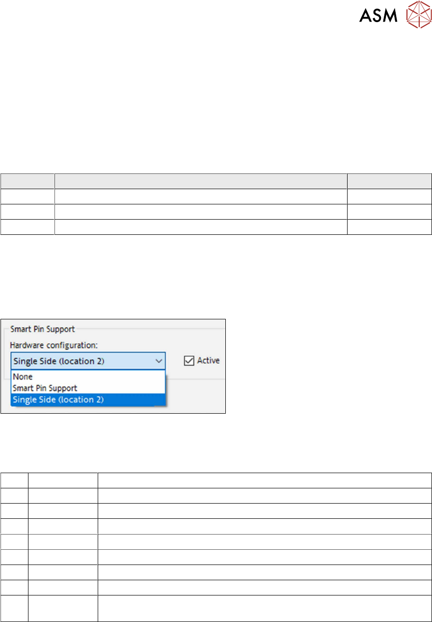
Fig.9: Setting
► Set the hardware configuration Single
Side (location2).
2.4 Tools and Equipment Required
T Standard tooling
T Rubber mallet
T 00376625Sxx Torque wrench 2.5-25 Nm with ratchet insert 1/4 inch
T07 03078400-xx Torque Screwdriver ESD 1.0-5.0 Nm
T78 03090019-xx Torque interchangeable blades 2.5 mm, hexagonal
T79 03109522-xx torque allen swap blade 3 mm
C08 00308458-xx Cable ties B=2.5mm, L=102mm Panduit
C38 00334892-xx LOCTITE 243 Screw locking
00198632-xx User manual "Operating and Configuring the SIPLACE Smart Pin Support
TX V2"
2.5 Required Working Time
Installing the hardware will take approx. 3 hours in total, installing the software approx. 1 hour.

2 Brief Description
2.5 Required Working Time
60 Assembly Instructions / Montageanleitung SIPLACE TX V2 Series Smart Pin Support 07/2021
3 Installation
3.1 Preparatory Steps
Assembly Instructions / Montageanleitung SIPLACE TX V2 Series Smart Pin Support 07/2021 61
3 Installation
DANGER
Observe the safety instructions!
When performing the following tasks, especially observe the safety instructions about work-
ing with strong magnetic fields.
► 1.1.2 "Safety instructions for working with strong magnetic fields" [}46]
3.1 Preparatory Steps
NOTICE
Preparation
Also read section 1.2 "Preparatory work..." [}49]
3.2 Converting the machine zero point
When a SIPLACE Tray Unit is installed, always observe the information in section 2.3.1 "Parts re-
quired for the SPS option in SIPLACE TX V2 machines with SIPLACE Tray Unit installed" [}59].
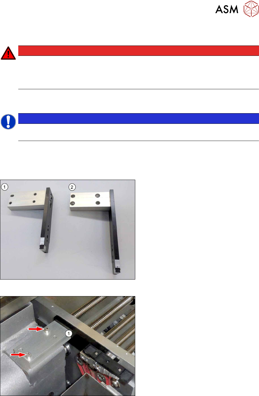
Fig.10: Overview of machine zero points
For operation with Smart Pin Support, the
machine zero point at location1 must be re-
placed.
1. Standard machine zero point
2. Smart Pin Support machine zero point
Fig.11: Dismantling the machine zero point
► Remove the two screws (M6xM16,
Allen5) and lift off the machine zero
point(1).