00198631-03_AI_Smart-Pin-Support_TX_DE_EN.pdf - 第56页
2 Brief Description 2.1 Product Description 56 Assembly Instructions / Montageanleitung SIPLACE TX V2 Series Smart Pin Support 07/2021 2.1.1 Configurations SIPLACE TX2i V2 Fig.6: Configuration SIPLACE SPS TX2i SIPLACE T…
2 Brief Description
2.1 Product Description
Assembly Instructions / Montageanleitung SIPLACE TX V2 Series Smart Pin Support 07/2021 55
2 Brief Description
Smart Pin Support facilitates automatic positioning of pins on the lifting table plate with the help of
the programming system. The pins can therefore be automatically positioned by the machine while
a new job is being downloaded to the machine.
2.1 Product Description
The "Smart Pin Support" option is available for TX2/TX2i V2 machines, from the serial number
TB072G.
The support pins are positioned on the lifting table plate with the help of SIPLACE Pro. The position
of these pins is described in SIPLACE Pro in the same way as in a placement list. The information
is then sent to the machine, together with the setup. The machine recognizes the available support
pins and sets these at the programmed positions.
The support pins are positioned with the help of two pin pickers. These pin pickers are each loc-
ated on the right side of the head holding plates of the gantries. At least two special feeders of the
type "Smart Pin Magazine T5" (pin feeder) provide the support pins. The feeders are automatically
recognized by the software and, at the same time, serve as table fiducials of the respective compo-
nent table.
Overview of parts
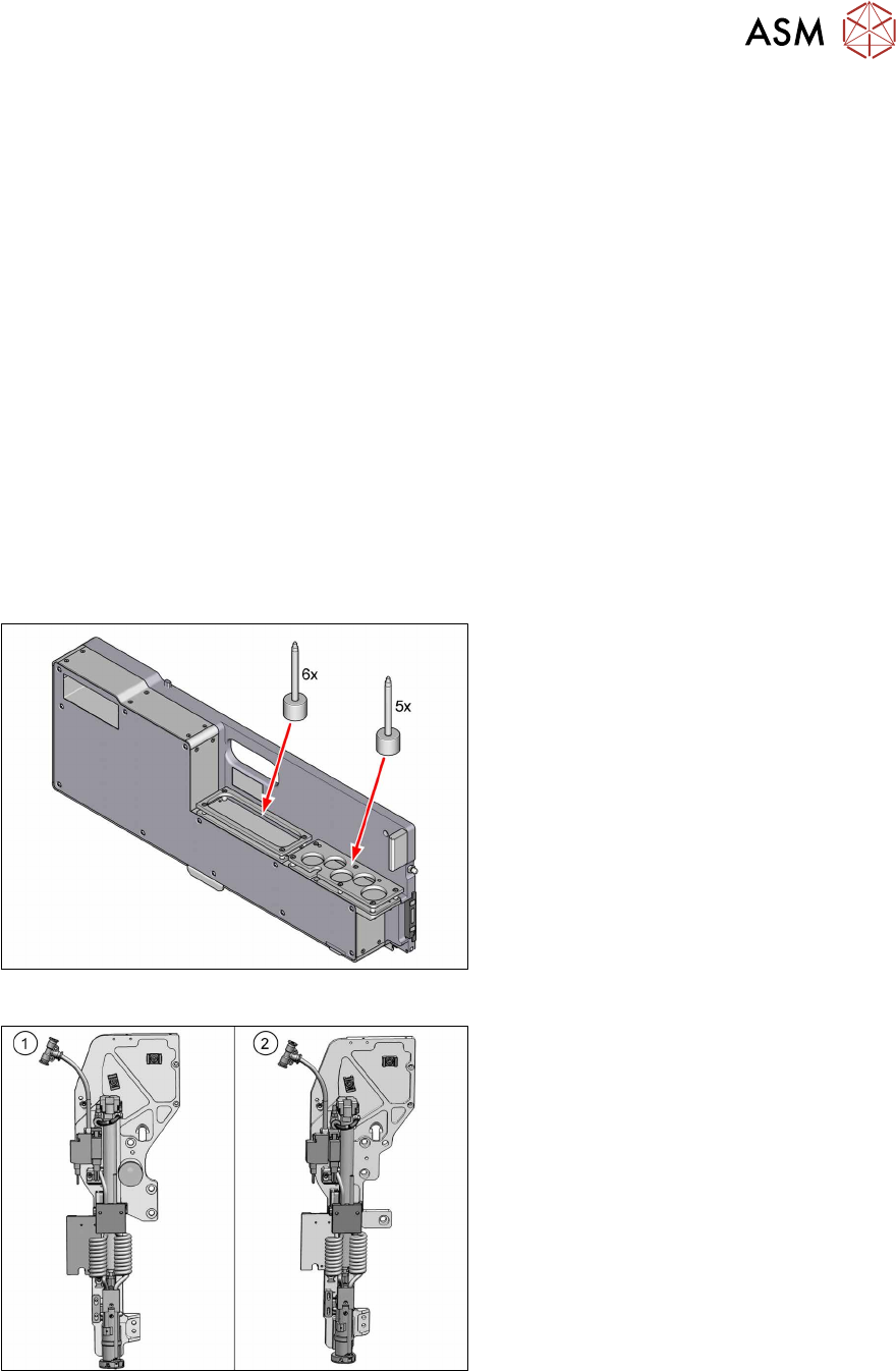
Fig.4: Pin feeder and support pins
Pin feeder [00588322‑xx]
At least one pin feeder is inserted in track 1
at each component trolley.
Support pins [03089582‑xx]
Each pin feeder can provide five supports
pins directly. Moreover, a pin feeder can
stock up to six additional support pins.
Fig.5: Pin picker
1. Pin picker gantry 1
[03165096‑xx]
2. Pin picker gantry 2
[03164367‑xx]
2 Brief Description
2.1 Product Description
56 Assembly Instructions / Montageanleitung SIPLACE TX V2 Series Smart Pin Support 07/2021
2.1.1 Configurations
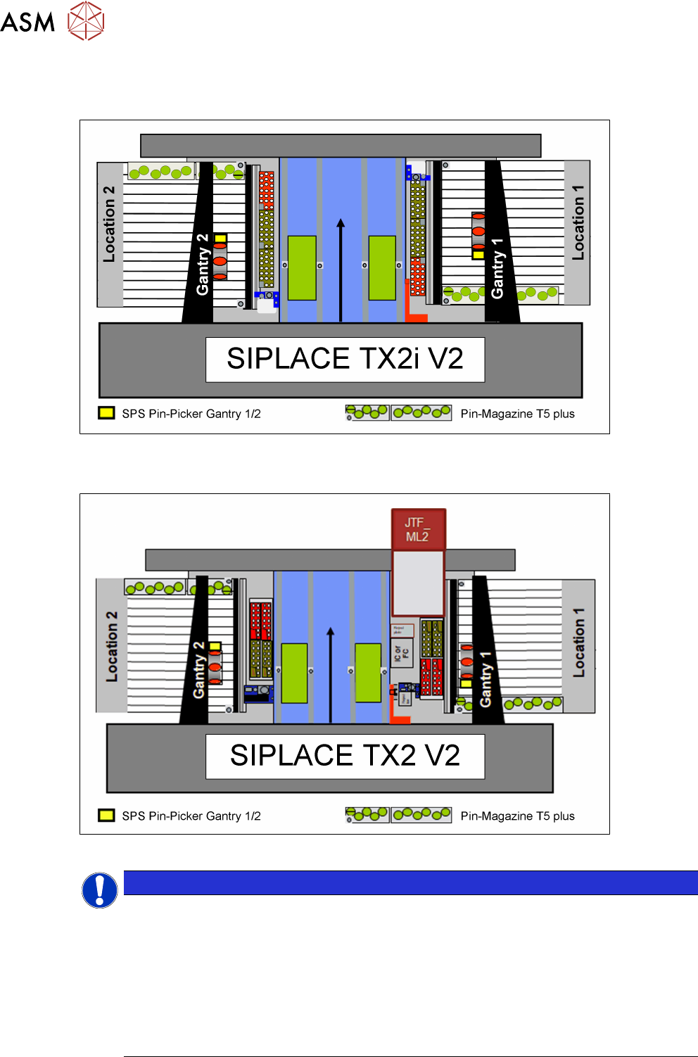
SIPLACE TX2i V2
Fig.6: Configuration SIPLACE SPS TX2i
SIPLACE TX2 V2
Fig.7: Configuration SIPLACE SPS TX2
NOTICE
New magazine with 3 fiducials
We recommend using the new magazine with 3 fiducials.
Nozzle magazine type 20xx/20 3 pos. fiducials [03226630‑xx]
Nozzle magazine type 40xx assy. / NCS [03218226‑xx]
This allows the magazines which would otherwise be unreachable to be reached in part
and also makes additional nozzles available.
► SIPLACE TX2i V2: additional 14 nozzles
► SIPLACE TX2 V2: additional 28 nozzles
2 Brief Description
2.2 Prerequisites and restrictions
Assembly Instructions / Montageanleitung SIPLACE TX V2 Series Smart Pin Support 07/2021 57
2.2 Prerequisites and restrictions
Requirements
●
SIPLACE TX2/TX2i V2 from serial number TB072G
●
SIPLACE CPP / SIPLACE C&P20P2
●
Station software 712.0x / SIPLACE Pro 16.x
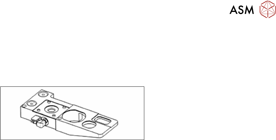
Fig.8: Nozzle station CPx complete
●
Nozzle station CPx assembly
[03106821‑xx]
All SIPLACE TX V2 machines with station-
ary camera and the large reject bin have this
nozzle station.
If this nozzle station has not yet been fitted,
you will need to replace the existing one.
Restrictions
●
Assembly is not possible on SIPLACE TX1 V2 machines.
●
In SIPLACE TX2i V2 machines, the NC magazine on the left in each case can either not be
used at both locations or can only be partially used.
●
In SIPLACE TX2 V2 machines, the two left NC magazines in each case can either not be
used at both locations or can only be partially used.
●
The six left lanes on each of the two component tables are occupied by a "Smart Pin
MagazineT5" (pin feeder). These may not be removed during operation as the table fiducial is
located on them.
Additional pin feeders can be placed up to and including track 25 and, if necessary, can be
removed.