00198631-03_AI_Smart-Pin-Support_TX_DE_EN.pdf - 第71页
3 Installation 3.4 Gantry 2 Assembly Instructions / Montageanleitung SIPLACE TX V2 Series Smart Pin Support 07/2021 71 Fig.35: Fitting the top spacer ► Fit the longer spacer at the top ( hand- tight, Loctite243 ). Fig.…
3 Installation
3.4 Gantry 2
70 Assembly Instructions / Montageanleitung SIPLACE TX V2 Series Smart Pin Support 07/2021
3.4 Gantry 2
3.4.1 Converting the X axis buffer
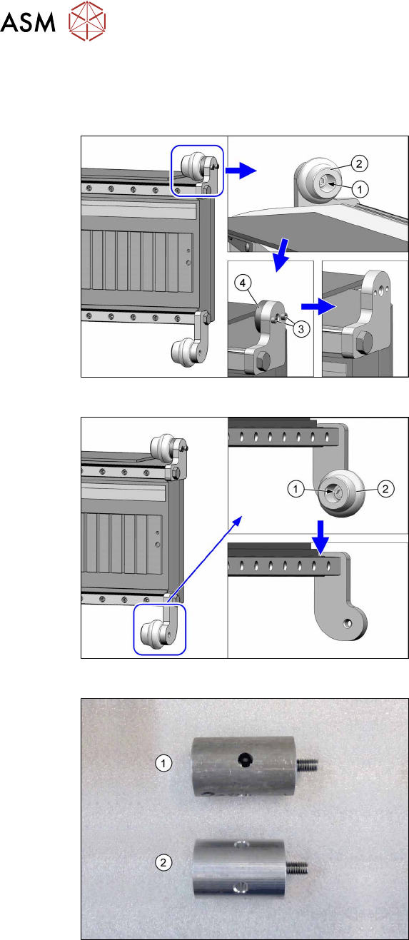
Fig.32: Removing the top rubber buffer
► Remove the screw(1) and take off the
top rubber buffer(2).
► Remove the two screws(3) (Allen2.5)
and lift off the spacer disk(4).
Fig.33: Removing the bottom rubber buffer
► Remove the screw(1) and take off the
bottom rubber buffer(2).
Fig.34: Top and bottom spacers
1. Top spacer
2. Bottom spacer
3 Installation
3.4 Gantry 2
Assembly Instructions / Montageanleitung SIPLACE TX V2 Series Smart Pin Support 07/2021 71
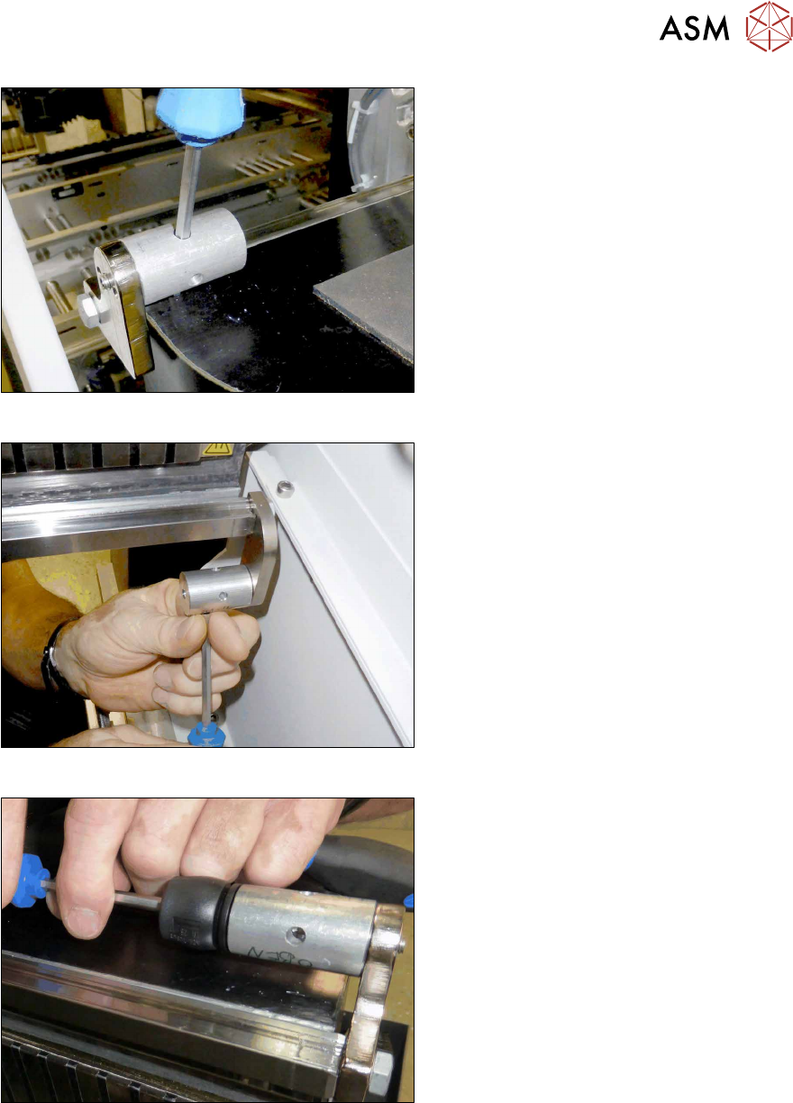
Fig.35: Fitting the top spacer
► Fit the longer spacer at the top (hand-
tight, Loctite243).
Fig.36: Fitting the bottom spacer
► Fit the shorter spacer at the bottom
(hand-tight, Loctite243).
Fig.37: Fitting the top buffer
► Fit a previously removed rubber buffer
to the top spacer (Loctite243).
► Fit the other previously removed rubber
buffer to the bottom spacer (Loc-
tite243).
3 Installation
3.4 Gantry 2
72 Assembly Instructions / Montageanleitung SIPLACE TX V2 Series Smart Pin Support 07/2021
3.4.2 Preparing the gantry
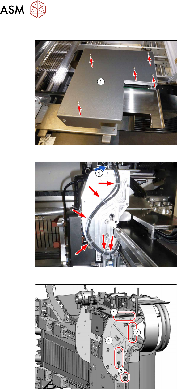
Fig.38: Board cover (using gantry1 as example)
► Remove the five fastening screws and
lift the board cover(1) off.
Fig.39: Unplugging the cable
► Loosen the cable ties.
► Unplug the cable at the head inter-
face(1).
Fig.40: Removing the side plate
► Remove the two screws(1) (M3x6,
Torx10).
► Remove the two screws(2) (M3x12,
Allen2.5).
► Remove the three screws(3) (M6x14,
Allen5) and lift off the side plate(4).