00198631-03_AI_Smart-Pin-Support_TX_DE_EN.pdf - 第68页
3 Installation 3.3 Gantry 1 68 Assembly Instructions / Montageanleitung SIPLACE TX V2 Series Smart Pin Support 07/2021 Fig.28: Shortening the hose ► Lift off the T piece and shorten the hose (1) (4x2.5PUN) of the pin …
3 Installation
3.3 Gantry 1
Assembly Instructions / Montageanleitung SIPLACE TX V2 Series Smart Pin Support 07/2021 67
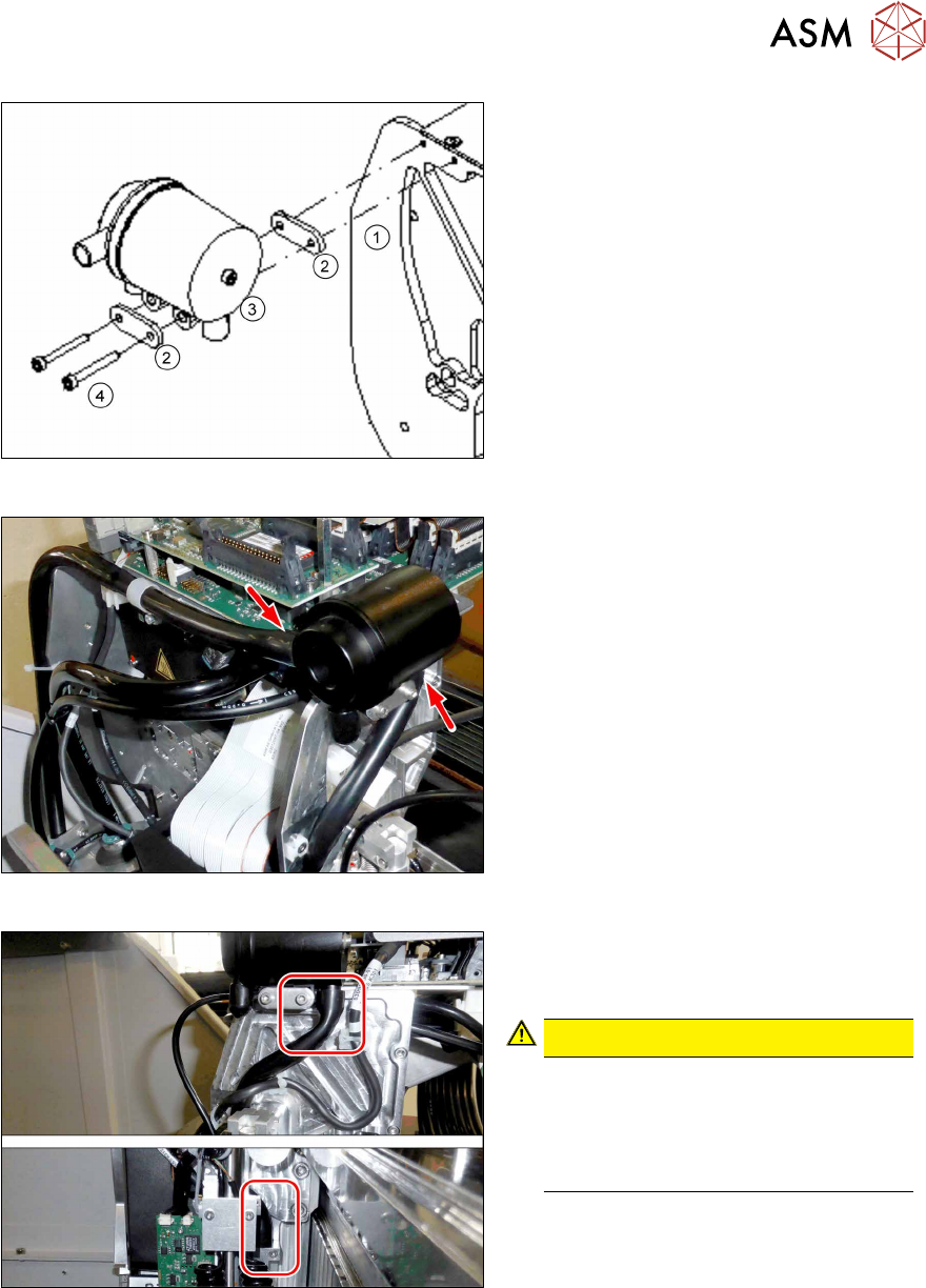
Fig.25: Mounting the silencer
1. Base plate of the pin picker
2. Disks
3. Silencer
4. 2x screws (M3x25, Allen key2.5,
Loctite243)
► Mount the silencer. Mind the two
disks(2).
Fig.26: Connecting the hoses
► Connect the two hoses to the silencer.
Fig.27: Checking the routing of the hose
► Makes sure that the hose is routed
properly, especially at the silencer and
the cooling.
CAUTION!
Routing of the hose
The hose may not be folded and must
sit tightly on the connections.
For this, press the hose completely
into the guide of the pin picker.
.
3 Installation
3.3 Gantry 1
68 Assembly Instructions / Montageanleitung SIPLACE TX V2 Series Smart Pin Support 07/2021
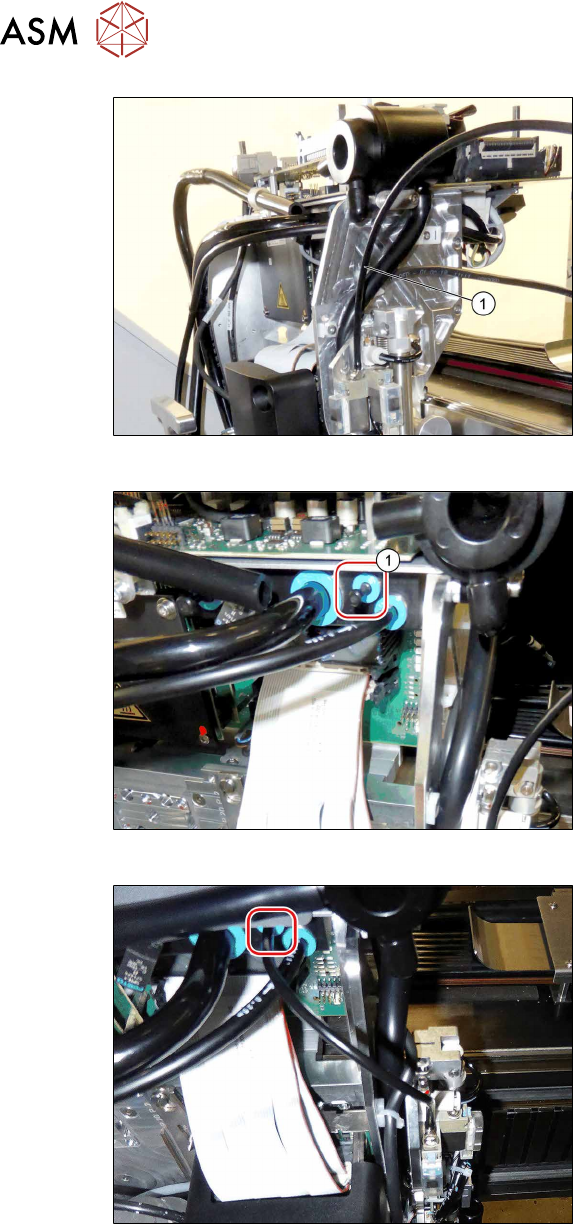
Fig.28: Shortening the hose
► Lift off the T piece and shorten the
hose(1) (4x2.5PUN) of the pin picker
by 170mm to a length of 180mm.
Fig.29: Removing the blanking plug
► Remove the blanking plug(1) at the
pneumatic distributor.
Fig.30: Connecting the hose
► Connect the hose to the pneumatic dis-
tributor.
3 Installation
3.3 Gantry 1
Assembly Instructions / Montageanleitung SIPLACE TX V2 Series Smart Pin Support 07/2021 69
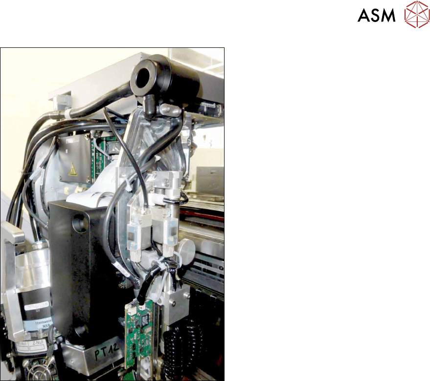
Fig.31: Running the cables
► Connect the "connection cable SPS TX
V2" [03208588‑xx] to the head inter-
face (X13).
► Make sure that the cable is run cor-
rectly.
► Secure the cables and hoses with
cable ties.