00198631-03_AI_Smart-Pin-Support_TX_DE_EN.pdf - 第75页
3 Installation 3.5 Smart Pin Magazine T5 (PinFeeder) Assembly Instructions / Montageanleitung SIPLACE TX V2 Series Smart Pin Support 07/2021 75 3.5 Smart Pin Magazine T5 (PinFeeder) Fig.46: Pin feeder At least one pin f…
3 Installation
3.4 Gantry 2
74 Assembly Instructions / Montageanleitung SIPLACE TX V2 Series Smart Pin Support 07/2021
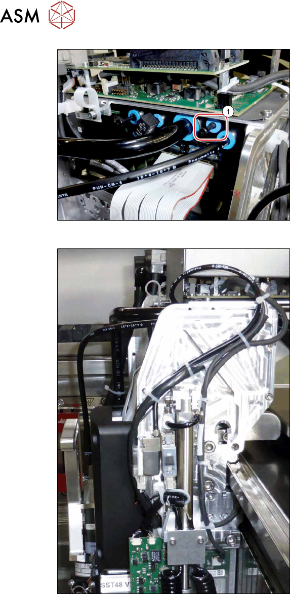
Fig.44: Removing the blanking plug
► Remove the blanking plug(1) at the
pneumatic distributor.
► Connect the hose of the pin picker to
the pneumatic distributor.
Fig.45: Running the cables
► Connect the "connection cable SPS TX
V2" [03208588‑xx] to the head inter-
face (X13).
► Make sure that the cable is run cor-
rectly.
► Secure the cables and hoses with
cable ties.
3 Installation
3.5 Smart Pin Magazine T5 (PinFeeder)
Assembly Instructions / Montageanleitung SIPLACE TX V2 Series Smart Pin Support 07/2021 75
3.5 Smart Pin Magazine T5 (PinFeeder)
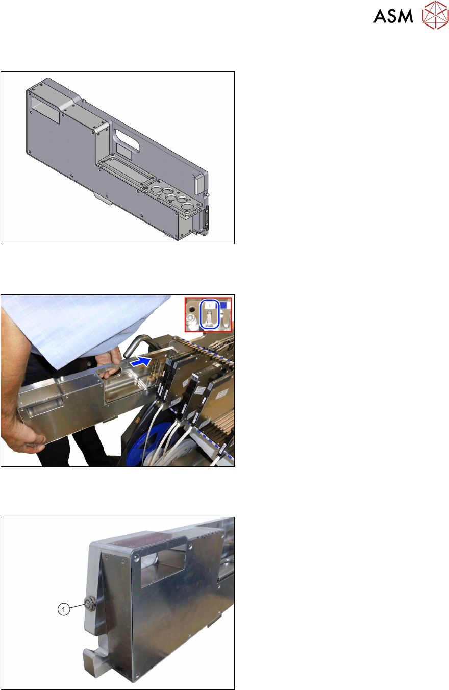
Fig.46: Pin feeder
At least one pin feeder must be inserted in
track 1 at each component table. You can
set up more than one pin feeder per compo-
nent table (up to and including track25).
The pin feeders on track1 must not be
removed from the component tables as they
provide the table fiducial. For the production,
additional pin feeders can be removed and
replaced by other feeders after the support
pins have been picked up.
Placing the pin feeder
Fig.47: Setting up the pin feeder
► Hold the pin feeder with both hands
and push it on track1 into the compo-
nent table.
ð The pin feeder is automatically re-
cognized and calibrated by the sta-
tion software. The button on the pin
feeder lights green.
ð If support pins are needed, these
will be automatically picked up and
placed.
Removing the pin feeder
Fig.48: Pin feeder button
► Press the button (1) on the pin feeder.
ð The pin feeder is logged off. The
button does not light any longer.
► Pull the pin feeder out of the compo-
nent table.
3 Installation
3.6 Final work
76 Assembly Instructions / Montageanleitung SIPLACE TX V2 Series Smart Pin Support 07/2021
3.6 Final work
When a SIPLACE Tray Unit is installed, always observe the information in section 2.3.1 "Parts re-
quired for the SPS option in SIPLACE TX V2 machines with SIPLACE Tray Unit installed" [}59].
Checks
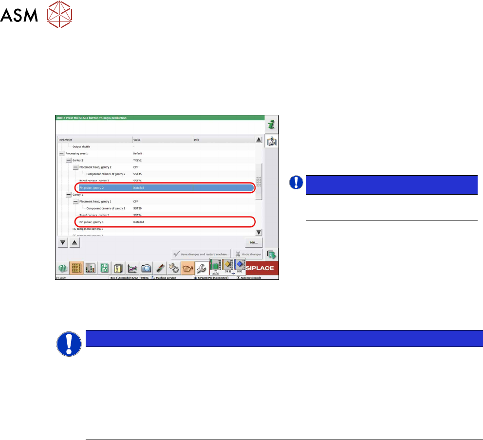
Fig.49: Checking the installation
► Refit the waste container.
► Switch on the machine.
► Check whether both pin pickers are set
to Installed in the station software.
NOTICE!
Check the connections if problems
occur.
.
Calibration
NOTICE
Calibration
Due to the changed machine zero point, the new table fiducials and the changed travel
ranges, the machine must be re-calibrated (machine zero point, x and Y travel ranges, PCB
reference corner).
► Read the following section.
► For more information, refer to the user manual "Operating and Configuring the Smart
Pin Support TX V2" [00198632‑xx].