00198631-03_AI_Smart-Pin-Support_TX_DE_EN.pdf - 第78页
3 Installation 3.6 Final work 78 Assembly Instructions / Montageanleitung SIPLACE TX V2 Series Smart Pin Support 07/2021 Fig.53: Saving the calibration ► Click on the Results… button for de- tails. ► Click on the Save b…
3 Installation
3.6 Final work
Assembly Instructions / Montageanleitung SIPLACE TX V2 Series Smart Pin Support 07/2021 77
3.6.1 Calibrating the pin pickers, lifting tables and pin feeders
► Start the Automatic Calibration in the Service view of the station software.
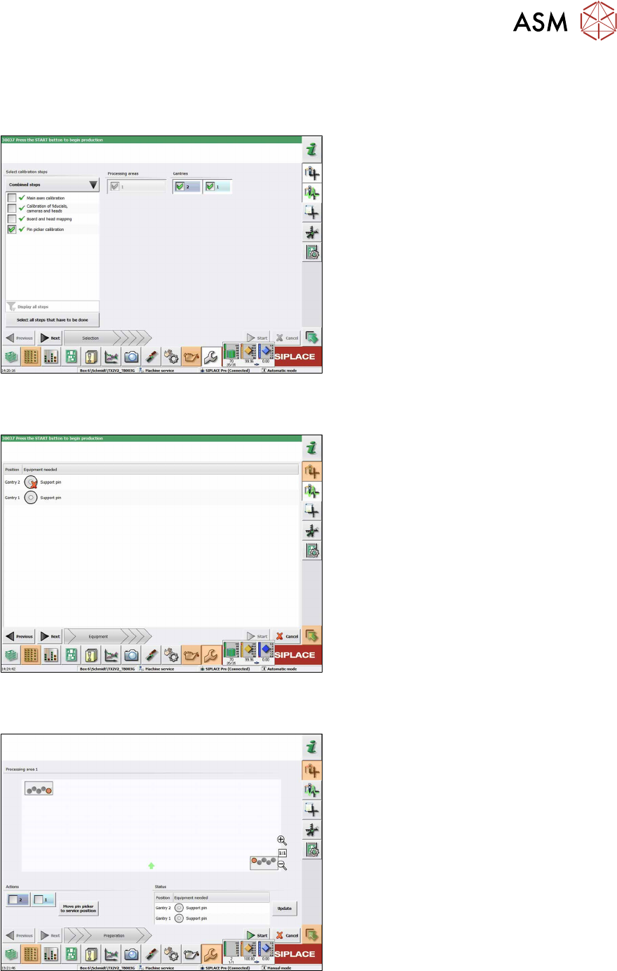
In the following dialog box you are prompted to select the required calibration steps.
Fig.50: Selecting the pin picker
► Select Select all steps that have to
be done to perform the calibrations
mentioned above.
or
► Select Select calibration steps →
Combined steps → Pin picker cali-
bration.
► Select Gantries.
► Click Next.
ð The conveyor width is automatically
set correctly, i.e. so that at least one
support pin can be placed on every
lifting table.
The following dialog box will appear if a support pin is missing:
Fig.51: Notification: Support pin missing
► Open the cover.
► Put the support pin into the pin picker.
► Close the cover.
► Click on the Continue button.
The following dialog box will appear if a calibration garage is occupied:
Fig.52: Notification: Calibration garage occupied
► Click on the Move pin picker to ser-
vice position button.
The gantry moves to the service position for
Smart Pin Support and you will be prompted
to remove the support pin from the garage
and put it into the pin picker.
► Open the cover.
► Remove the support pin from the cali-
bration garage.
► Close the cover.
► Click on the Continue button.
► Once all preconditions have been ful-
filled, click on the Start button.
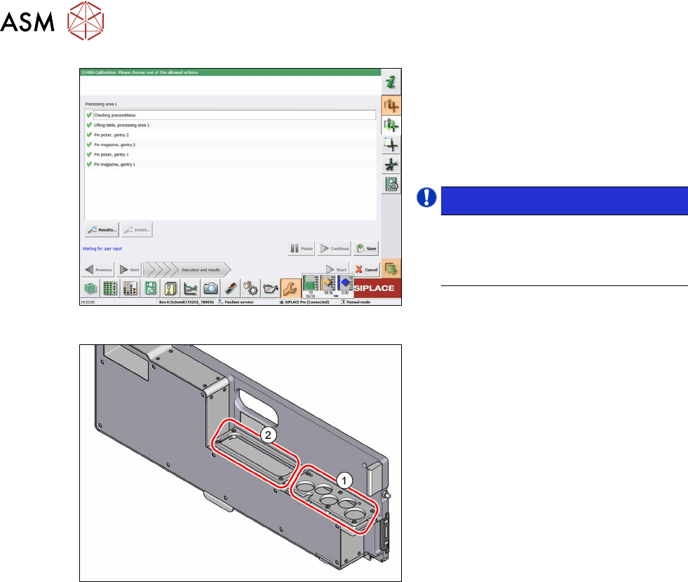
In the following dialog box the calibration result is displayed.
3 Installation
3.6 Final work
78 Assembly Instructions / Montageanleitung SIPLACE TX V2 Series Smart Pin Support 07/2021
Fig.53: Saving the calibration
► Click on the Results… button for de-
tails.
► Click on the Save button to apply the
calibration data.
► Click on the Close button to exit the
calibration.
NOTICE!
Filling the pin feeder
After being successfully calibrated, the
pin feeder garages can be filled with
support pins.
.
Fig.54: Pin feeder areas for support pins
1. Up to five support pins can be placed in
the garages in the front area. These
support pins can be automatically
picked up by the pin picker.
2. In the back area, additional support
pins can be parked. These can then be
brought forward manually when re-
quired and placed into the garages.

4 Appendix
4.1 Circuit Diagrams
Assembly Instructions / Montageanleitung SIPLACE TX V2 Series Smart Pin Support 07/2021 79
4 Appendix
4.1 Circuit Diagrams
For more information, refer to the circuit diagrams folder:
●
Detailed circuit diagrams SIPLACE TX V2-Series [DE+EN: 00198460-xx]