00198631-03_AI_Smart-Pin-Support_TX_DE_EN.pdf - 第61页
3 Installation 3.1 Preparatory Steps Assembly Instructions / Montageanleitung SIPLACE TX V2 Series Smart Pin Support 07/2021 61 3 Installation DANGER Observe the safety instructions! When performing the following tasks, …

2 Brief Description
2.5 Required Working Time
60 Assembly Instructions / Montageanleitung SIPLACE TX V2 Series Smart Pin Support 07/2021
3 Installation
3.1 Preparatory Steps
Assembly Instructions / Montageanleitung SIPLACE TX V2 Series Smart Pin Support 07/2021 61
3 Installation
DANGER
Observe the safety instructions!
When performing the following tasks, especially observe the safety instructions about work-
ing with strong magnetic fields.
► 1.1.2 "Safety instructions for working with strong magnetic fields" [}46]
3.1 Preparatory Steps
NOTICE
Preparation
Also read section 1.2 "Preparatory work..." [}49]
3.2 Converting the machine zero point
When a SIPLACE Tray Unit is installed, always observe the information in section 2.3.1 "Parts re-
quired for the SPS option in SIPLACE TX V2 machines with SIPLACE Tray Unit installed" [}59].
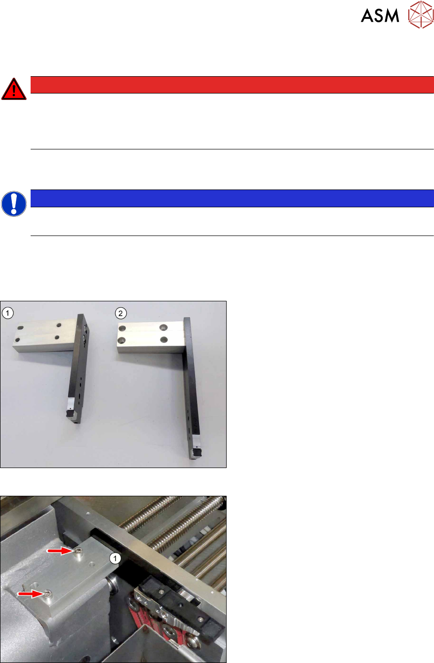
Fig.10: Overview of machine zero points
For operation with Smart Pin Support, the
machine zero point at location1 must be re-
placed.
1. Standard machine zero point
2. Smart Pin Support machine zero point
Fig.11: Dismantling the machine zero point
► Remove the two screws (M6xM16,
Allen5) and lift off the machine zero
point(1).
3 Installation
3.2 Converting the machine zero point
62 Assembly Instructions / Montageanleitung SIPLACE TX V2 Series Smart Pin Support 07/2021
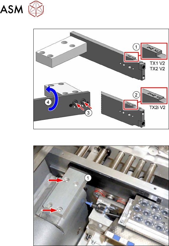
Fig.12: Checking/adjusting the machine zero point
► Check if the new machine zero point is
correctly configured for your machine.
1. TX Z = 0
for SIPLACE TX1 V2
and SIPLACE TX2 V2
2. TX Z = +2
for SIPLACE TX2i V2
The value for your machine must be located
on top.
If the machine zero point does not match the
machine type, proceed as follows:
► Remove the two screws(3) (ISO8734
M5x18) and lift off the rail(4).
► Rotate the rail by 180° and refit it.
Fig.13: Fitting the machine zero point
► Fasten the new machine zero point(1)
with two screws (Loctite243).
If possible, use new screws.