00198631-03_AI_Smart-Pin-Support_TX_DE_EN.pdf - 第73页
3 Installation 3.4 Gantry 2 Assembly Instructions / Montageanleitung SIPLACE TX V2 Series Smart Pin Support 07/2021 73 3.4.3 Installing the pin picker Fig.41: Inserting the pin picker ► Place the pin picker (including t…
3 Installation
3.4 Gantry 2
72 Assembly Instructions / Montageanleitung SIPLACE TX V2 Series Smart Pin Support 07/2021
3.4.2 Preparing the gantry
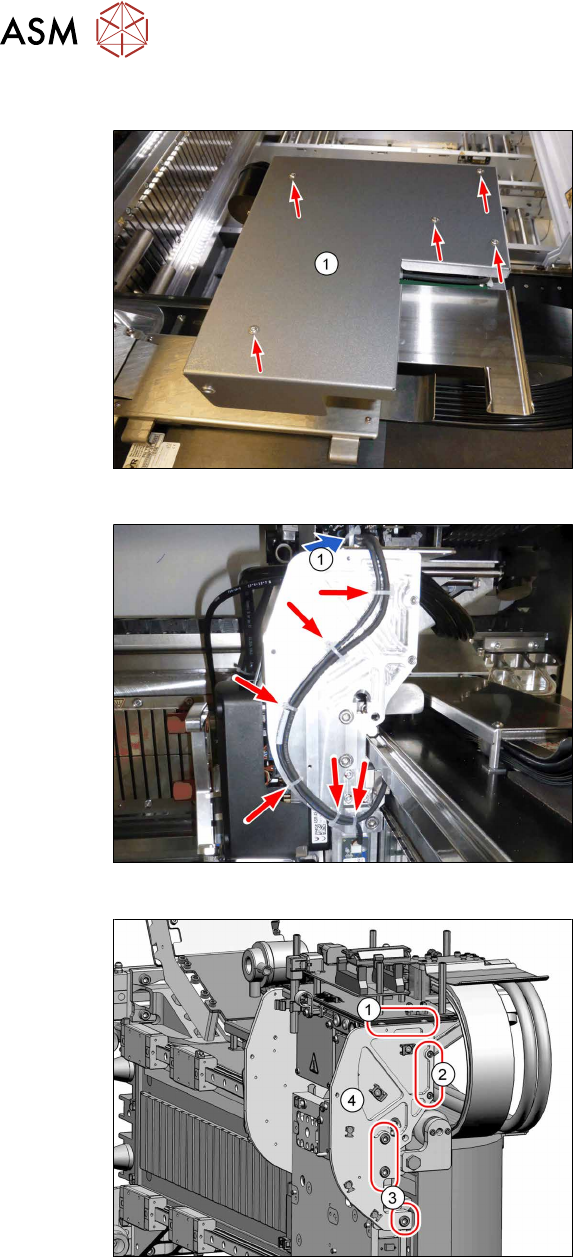
Fig.38: Board cover (using gantry1 as example)
► Remove the five fastening screws and
lift the board cover(1) off.
Fig.39: Unplugging the cable
► Loosen the cable ties.
► Unplug the cable at the head inter-
face(1).
Fig.40: Removing the side plate
► Remove the two screws(1) (M3x6,
Torx10).
► Remove the two screws(2) (M3x12,
Allen2.5).
► Remove the three screws(3) (M6x14,
Allen5) and lift off the side plate(4).
3 Installation
3.4 Gantry 2
Assembly Instructions / Montageanleitung SIPLACE TX V2 Series Smart Pin Support 07/2021 73
3.4.3 Installing the pin picker
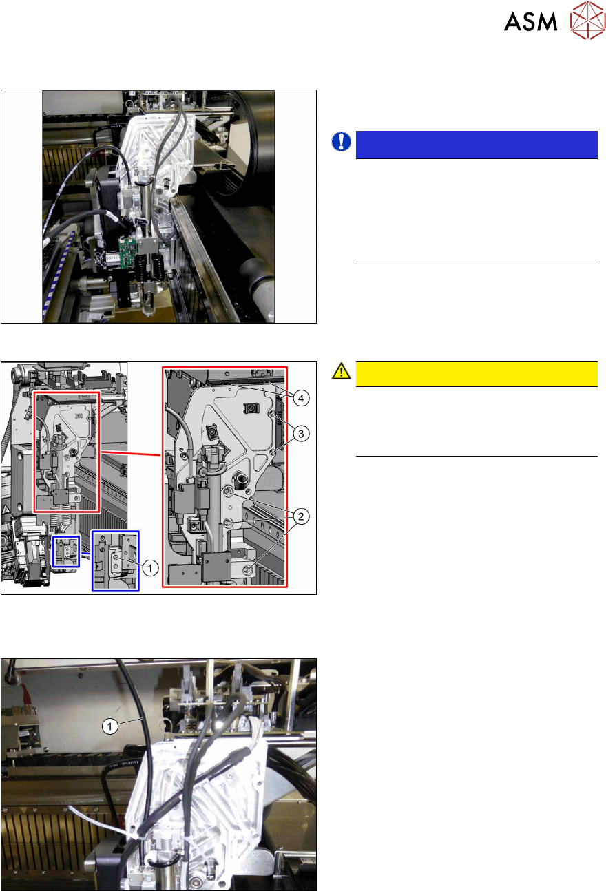
Fig.41: Inserting the pin picker
► Place the pin picker (including the side
plate) on the gantry.
NOTICE!
Centering pins
The pin picker has two centering pins.
First, position the bottom centering pin
and after that the top one.
The base plate of the pin picker must
fit closely.
.
Fig.42: Fastening the pin picker
CAUTION!
Observe the specified order
To minimize tension, first tighten the
screws(1) to(3) and after that the top
screws(4).
.
► Fasten the pin picker with eight screws:
1. 1x M4x14, Allen3
Torque 2.9Nm, Loctite243
2. 3x M6x14, Allen5
Torque 10Nm, Loctite243
3. 2x M3x12, Allen2.5
Torque 1.3Nm, Loctite243
4. 2x M3x6, Torx10, button head
[03119157‑xx]
Loctite243
Fig.43: Shortening the hose
► Lift off the T piece and shorten the
hose(1) (4x2.5PUN) of the pin picker
by 70mm to a length of 280mm.
3 Installation
3.4 Gantry 2
74 Assembly Instructions / Montageanleitung SIPLACE TX V2 Series Smart Pin Support 07/2021
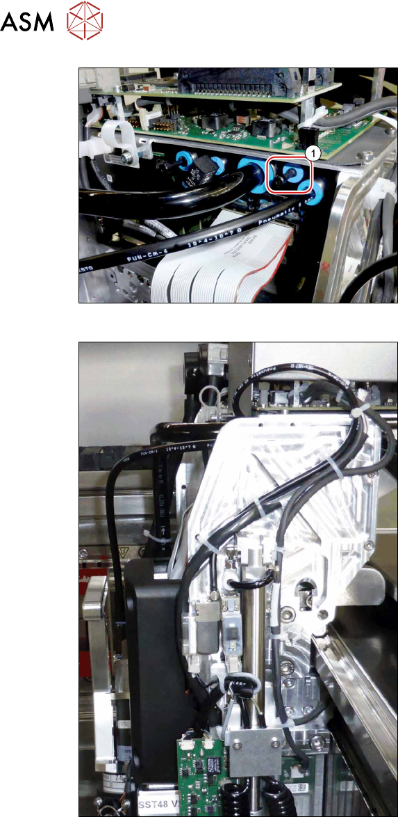
Fig.44: Removing the blanking plug
► Remove the blanking plug(1) at the
pneumatic distributor.
► Connect the hose of the pin picker to
the pneumatic distributor.
Fig.45: Running the cables
► Connect the "connection cable SPS TX
V2" [03208588‑xx] to the head inter-
face (X13).
► Make sure that the cable is run cor-
rectly.
► Secure the cables and hoses with
cable ties.