00198631-03_AI_Smart-Pin-Support_TX_DE_EN.pdf - 第65页
3 Installation 3.3 Gantry 1 Assembly Instructions / Montageanleitung SIPLACE TX V2 Series Smart Pin Support 07/2021 65 Fig.20: Removing the cooling ► Remove the two screws (Allen2.5) and lift off the air connection (1…
3 Installation
3.3 Gantry 1
64 Assembly Instructions / Montageanleitung SIPLACE TX V2 Series Smart Pin Support 07/2021
3.3.3 Preparing the gantry
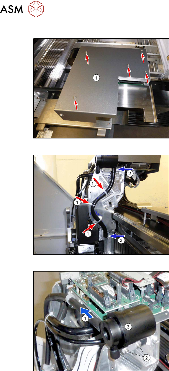
Fig.17: Board cover
► Remove the five fastening screws and
lift the board cover(1) off.
Fig.18: Disconnecting the exhaust air hose
► Loosen the cable ties(1).
► Disconnect the exhaust air hose from
the silencer(2) (top) and from the air
connection(3) for cooling the X motor
plate (bottom),
Fig.19: Removing the silencer
► Disconnect the hose(1) from the silen-
cer(3).
► Remove the two screws(2) (Allen2.5,
M3x25) and lift off the silencer.
Make sure not to lose the two disks.
3 Installation
3.3 Gantry 1
Assembly Instructions / Montageanleitung SIPLACE TX V2 Series Smart Pin Support 07/2021 65
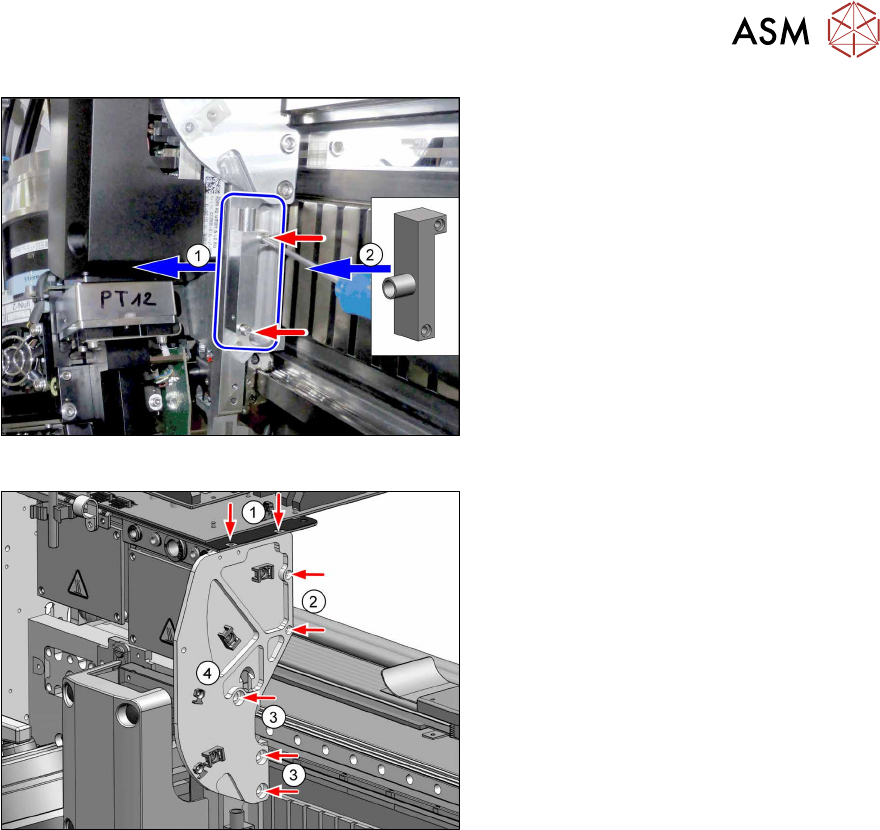
Fig.20: Removing the cooling
► Remove the two screws (Allen2.5) and
lift off the air connection(1) for cooling
the X motor plate.
► Fit the new air connection(2)
[03210185-xx] with two screws (M3x14,
Allen2.5, torque 1.3Nm, Loctite241).
Fig.21: Removing the plate
► Remove the two screws(1) (M3x6, but-
ton head, Torx10).
► Remove the two screws(2) (M3x12,
Allen2.5).
► Remove the three screws(3) (M6x14,
Allen5) and lift off the side plate of the
X holder(4).
3 Installation
3.3 Gantry 1
66 Assembly Instructions / Montageanleitung SIPLACE TX V2 Series Smart Pin Support 07/2021
3.3.4 Installing the pin picker
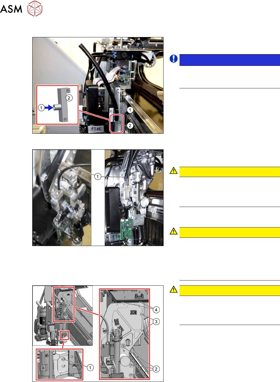
Fig.22: Connecting the hose
► Fit the hose(1) on the air connec-
tion(2) for cooling the X motor plate.
NOTICE!
New exhaust air hose for gantry 1
Use the silicone hose from the retrofit
kit with a length of 310mm.
.
Fig.23: Feeding in the hose
► Feed in the hose(1) through the pin
picker.
CAUTION!
Hose
Press the hose all the way down and
into the pin picker.
The hose must not be folded.
.
► Place the pin picker (including the base
plate) on the X holder.
CAUTION!
Centering pins
The pin picker has two centering pins.
First, position the bottom centering pin
and after that the top one.
The base plate of the pin picker must
fit closely.
.
Fig.24: Fastening the pin picker
CAUTION!
Observe the specified order
To minimize tension, first tighten the
screws(1) to(3) and after that the top
screws(4).
.
► Fasten the pin picker with eight screws:
1. 1x M4x14, Allen3
Torque 2.9Nm, Loctite243
2. 3x M6x14, Allen5
Torque 10Nm, Loctite243
3. 2x M3x12, Allen2.5
Torque 1.3Nm, Loctite243
4. 2x M3x6, Torx10 [03119157‑xx]
Torque 1.3Nm, Loctite243