00198631-03_AI_Smart-Pin-Support_TX_DE_EN.pdf - 第69页
3 Installation 3.3 Gantry 1 Assembly Instructions / Montageanleitung SIPLACE TX V2 Series Smart Pin Support 07/2021 69 Fig.31: Running the cables ► Connect the "connection cable SPS TX V2" [03208588‑xx] to the…
3 Installation
3.3 Gantry 1
68 Assembly Instructions / Montageanleitung SIPLACE TX V2 Series Smart Pin Support 07/2021
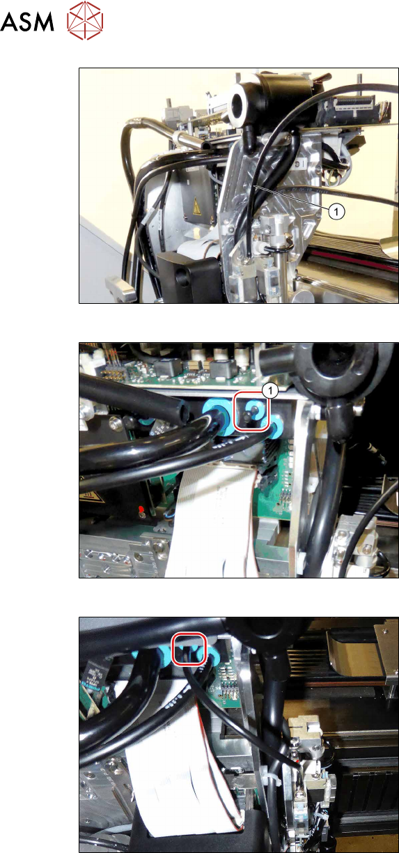
Fig.28: Shortening the hose
► Lift off the T piece and shorten the
hose(1) (4x2.5PUN) of the pin picker
by 170mm to a length of 180mm.
Fig.29: Removing the blanking plug
► Remove the blanking plug(1) at the
pneumatic distributor.
Fig.30: Connecting the hose
► Connect the hose to the pneumatic dis-
tributor.
3 Installation
3.3 Gantry 1
Assembly Instructions / Montageanleitung SIPLACE TX V2 Series Smart Pin Support 07/2021 69
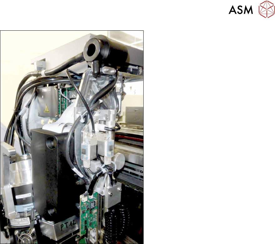
Fig.31: Running the cables
► Connect the "connection cable SPS TX
V2" [03208588‑xx] to the head inter-
face (X13).
► Make sure that the cable is run cor-
rectly.
► Secure the cables and hoses with
cable ties.
3 Installation
3.4 Gantry 2
70 Assembly Instructions / Montageanleitung SIPLACE TX V2 Series Smart Pin Support 07/2021
3.4 Gantry 2
3.4.1 Converting the X axis buffer
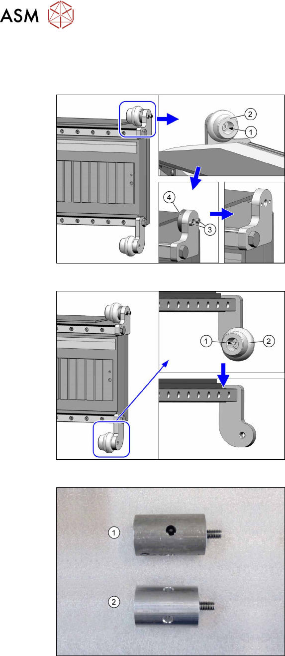
Fig.32: Removing the top rubber buffer
► Remove the screw(1) and take off the
top rubber buffer(2).
► Remove the two screws(3) (Allen2.5)
and lift off the spacer disk(4).
Fig.33: Removing the bottom rubber buffer
► Remove the screw(1) and take off the
bottom rubber buffer(2).
Fig.34: Top and bottom spacers
1. Top spacer
2. Bottom spacer