00198631-03_AI_Smart-Pin-Support_TX_DE_EN.pdf - 第79页
4 Appendix 4.1 Circuit Diagrams Assembly Instructions / Montageanleitung SIPLACE TX V2 Series Smart Pin Support 07/2021 79 4 Appendix 4.1 Circuit Diagrams For more information, refer to the circuit diagrams folder: ● Det…
3 Installation
3.6 Final work
78 Assembly Instructions / Montageanleitung SIPLACE TX V2 Series Smart Pin Support 07/2021
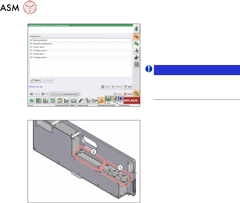
Fig.53: Saving the calibration
► Click on the Results… button for de-
tails.
► Click on the Save button to apply the
calibration data.
► Click on the Close button to exit the
calibration.
NOTICE!
Filling the pin feeder
After being successfully calibrated, the
pin feeder garages can be filled with
support pins.
.
Fig.54: Pin feeder areas for support pins
1. Up to five support pins can be placed in
the garages in the front area. These
support pins can be automatically
picked up by the pin picker.
2. In the back area, additional support
pins can be parked. These can then be
brought forward manually when re-
quired and placed into the garages.

4 Appendix
4.1 Circuit Diagrams
Assembly Instructions / Montageanleitung SIPLACE TX V2 Series Smart Pin Support 07/2021 79
4 Appendix
4.1 Circuit Diagrams
For more information, refer to the circuit diagrams folder:
●
Detailed circuit diagrams SIPLACE TX V2-Series [DE+EN: 00198460-xx]

4 Appendix
4.1 Circuit Diagrams
80 Assembly Instructions / Montageanleitung SIPLACE TX V2 Series Smart Pin Support 07/2021