00198374-02_UG_OSC-Paket_R18-2_DE_EN.pdf - 第60页
3 Prerequisites 3.2 Hardware Requirements 60 Bedienungsanleitung OSC Package User Guide OSC-Paket 11/2018 Function Hardware Placement of an exeptionally high component (1 use case) Placement machine: SIPLACE SX V2 Single…

3 Prerequisites
3.1 Software Requirements
Bedienungsanleitung OSC Package User Guide OSC-Paket 11/2018 59
3 Prerequisites
The necessary system requirements for the OSC package correspond to the system requirements
for SIPLACE Pro and are described in the SIPLACE Pro Version Description,
item no. [00198612-xx] .
3.1 Software Requirements
The following software requirements must be met for the released features of R16-2:
●
SIPLACE Pro from Version 14.0 (R16-2)
●
Station software from Version 710.0 (R16-2)
●
SIPLACE Vision from Version 5.4.1 (R16-2)
The following software requirements must be met for the released features of R18-2:
●
SIPLACE Pro from Version 16.0 (R18-2)
●
Station software from Version 712.0 (R18-2)
●
SIPLACE Vision from Version 5.6.1 (R18-2)
3.2 Hardware Requirements
The following hardware requirements must be met for the released features of R16-2:
Function Hardware
Improved placement of snap-in components Placement heads: : Twin VHF
Smart Pin Support is recommended
Stereo Measurement for THT Pins Placement heads: CPP, TH, TH HF,
Twin VHF
Camera types: SST33, SST25
Customer-specific Pattern Features Placement heads: All
Special position evaluation Placement heads: All
Support to find best acceleration Placement heads: All
Increased placement force for Twin VHF placement
head to 100 N
Placement head: Twin VHF
Can only be used with function status
-03!
Smart Pin Support is recommended
The following hardware requirements must be met for the released features of R18-2:
Function Hardware
Improved placement of components with centering pins
(Pin in Paste height check)
Placement heads: CPP, TH, Twin VHF
Smart Pin Support is recommended
Improved teaching of snap-in components Placement head: Twin VHF
Stereo measurement for Gullwing and Pattern
Features lead group types
Placement heads: CPP, TH, TH HF,
Twin VHF
Camera types: SST33, SST25
Measurement parameter 4x image capture as option in
the stereo measurement
Placement heads: CPP, TH, TH HF,
Twin VHF
Camera types: SST33, SST25
Automatic illumination optimization for Non-standard
and Connector component types
Placement heads: All
3 Prerequisites
3.2 Hardware Requirements
60 Bedienungsanleitung OSC Package User Guide OSC-Paket 11/2018
Function Hardware
Placement of an exeptionally high component
(1 use case)
Placement machine: SIPLACE SX V2
Single conveyor
Placement head: only Twin VHF or
Twin VHF and Twin VHF or
Twin VHF and CPP in higher position
One component of type SMT;
Height: max. 46 mm
or
One component of type THT (e.g. Con-
nector or Inductance);
Height: max. 46 mm without protruding
elements which disappear into the board
after placement (e.g. centering pins), 50
mm with protruding elements
Increased placement force for TH placement head to
30 N (as for TH HF)
Placement head: TH
Smart Pin Support is recommended
4 Working with the OSC Features
4.1 Placement of Snap-In Components (from R16-2)
Bedienungsanleitung OSC Package User Guide OSC-Paket 11/2018 61
4 Working with the OSC Features
This chapter describes how to work with the single OSC features. The section headings display
from which release the respective function is supported.
► Make use of the information provided in the Online Help files for SIPLACE Pro and the station
software. These files contain additional, detailed information about the OSC features.
4.1 Placement of Snap-In Components (from R16-2)
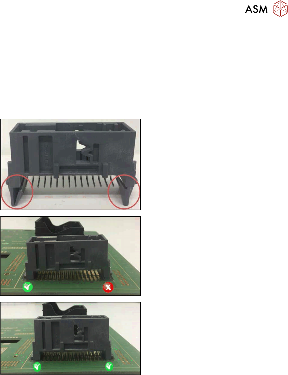
When placing snap-in components, it must be ensured that the components lock correctly into the
board. The system can verify this by an improved method.
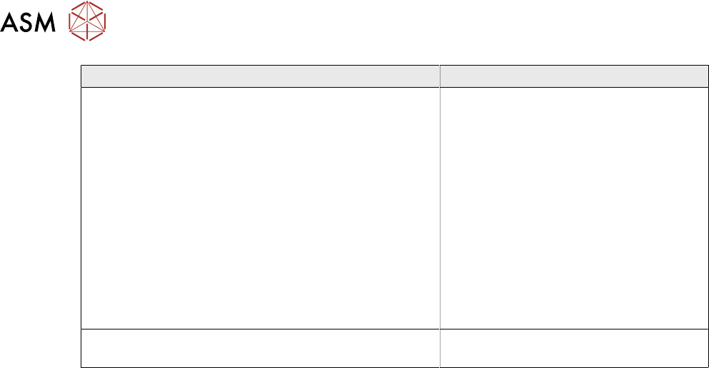
Example
Snap-in component
Snap-in component – not placed correctly
Snap-in component – placed correctly
The actual Z-axis position of every snap-in placement will be compared with its corresponding
height reference value during the verification. These values must match each other.
The snap-in placement process has to be enabled for the component shape in SIPLACE Pro. Addi-
tionally, the snap-in threshold that shall be used for comparing the two values has to be specified.