00198374-02_UG_OSC-Paket_R18-2_DE_EN.pdf - 第69页
4 Working with the OSC Features 4.2 Stereo Measurement for THT Pins (from R16-2) Bedienungsanleitung OSC Package User Guide OSC-Paket 11/2018 69 4.2.1 Procedure The following overview lists the single work steps that hav…

4 Working with the OSC Features
4.2 Stereo Measurement for THT Pins (from R16-2)
68 Bedienungsanleitung OSC Package User Guide OSC-Paket 11/2018
●
Maximum component size: the rules for the normal 2D measurement minus the traverse path
are applied. The result for the default traverse path
(8 mm for camera type 25, 18 mm for camera type 33) is:
Camera type 25: maximum 55 mm – 8 mm = 47 mm edge length
Camera type 33: maximum 85 mm – 18 mm = 67 mm edge length (or (200 mm – 18 mm) x
(125 mm – 18 mm) = 182 mm x 107 mm with restrictions)
These values refer to the multiple measurement.
●
Supported placement heads:
Twin Head (all high force variants included)
CPP (in Pick&Place mode, if equipped with stationary camera)

4 Working with the OSC Features
4.2 Stereo Measurement for THT Pins (from R16-2)
Bedienungsanleitung OSC Package User Guide OSC-Paket 11/2018 69
4.2.1 Procedure
The following overview lists the single work steps that have to be performed in the specified order
to perform the stereo measurement when THT components are placed.
Performing Stereo Measurement
Step Action SIPLACE program
1) Enabling OSC package SIPLACE Pro
2) Setting component height (overall height and creep distance) –
Observing focus height
SIPLACE Pro
3) If a nozzle gripper is used, setting the nozzle height SIPLACE Pro
4) Enabling stereo measurement for THT pins SIPLACE Vision
5) If necessary, changing the traverse path in the stereo height
view
SIPLACE Vision
4 Working with the OSC Features
4.2 Stereo Measurement for THT Pins (from R16-2)
70 Bedienungsanleitung OSC Package User Guide OSC-Paket 11/2018
4.2.2 Application Example
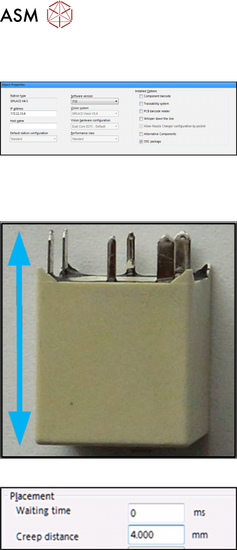
Step 1: SIPLACE Pro
► In the Station Editor under Placement Station,
enable the OSC Package option under Installed
options.
In SIPLACE Pro the component height has to be set so that the THT pin tips are located in the
focal plane of the camera. In the focal plane, the THT pin tips are displayed most sharply, and the
measurement is most accurate. For this, the following settings are required:
Step 2: Setting overall height – SIPLACE Pro
Setting the component overall height (from the pin tips
to the component bottom).
► In the Component Shape Editor, set the compo-
nent overall height under Component Shape –
Form – Overall height (with pins).
Step 2: Setting creep distance – SIPLACE Pro
Setting creep distance = THT pin length
► In SIPLACE Pro Desk, set the creep distance =
THT pin length under Handling – Placement –
Creep Distance.
If you use a nozzle gripper, the nozzle height also has to be set.