00198374-02_UG_OSC-Paket_R18-2_DE_EN.pdf - 第88页
4 Working with the OSC Features 4.6 Placement of Components with Centering Pins – PininPaste Height Check (from R18-2) 88 Bedienungsanleitung OSC Package User Guide OSC-Paket 11/2018 4.6.1 Procedure The following overv…

4 Working with the OSC Features
4.6 Placement of Components with Centering Pins – PininPaste Height Check (from R18-2)
Bedienungsanleitung OSC Package User Guide OSC-Paket 11/2018 87
4.6 Placement of Components with Centering Pins –
PininPaste Height Check (from R18-2)
When placing components with centering pins, it must be ensured that the centering pins fit into the
corresponding holes on the board. The same procedure is used for the verification as for the place-
ment of snap-in components, but with less placement force.

4 Working with the OSC Features
4.6 Placement of Components with Centering Pins – PininPaste Height Check (from R18-2)
88 Bedienungsanleitung OSC Package User Guide OSC-Paket 11/2018
4.6.1 Procedure
The following overview lists the single work steps that have to be performed in the specified order
to place components with centering pins (Pin in Paste height check).
Placement of components with centering pins (Pin in Paste height check)
Step Action SIPLACE program
1) Enabling OSC package SIPLACE Pro
2) Selecting the Standard placement process for the component
shape
SIPLACE Pro
3) Enabling Pin in Paste height check SIPLACE Pro
4) Setting Z-threshold (Default: 0.500 mm) SIPLACE Pro
5) If necessary, configuring the inspection station (Default:
Output section)
Station Software
6) Verifying and confirming all placement positions at the inspec-
tion station
Station Software
4 Working with the OSC Features
4.6 Placement of Components with Centering Pins – PininPaste Height Check (from R18-2)
Bedienungsanleitung OSC Package User Guide OSC-Paket 11/2018 89
4.6.2 Application Example
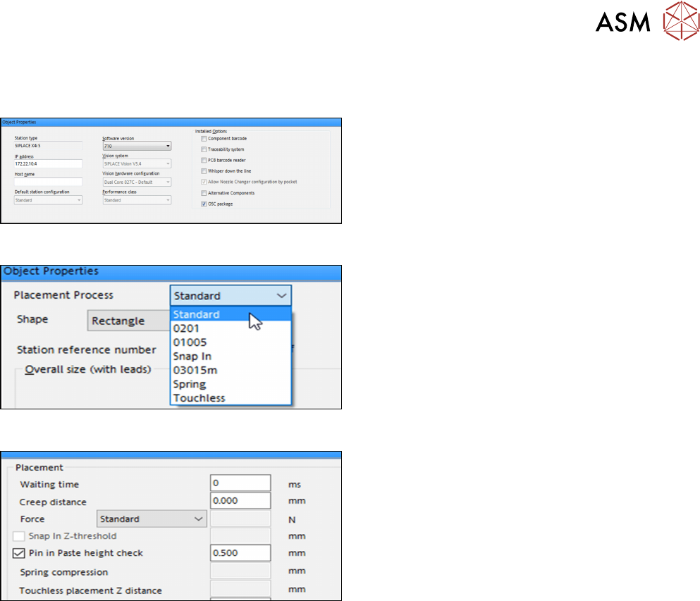
Step 1: SIPLACE Pro
► In the Station Editor under Placement Station,
enable the OSC Package option under Installed
options.
Step 2: SIPLACE Pro
► In the Component Shape Editor, select the
Standard feature as placement process for the
component shape.
Step 3 and Step 4: SIPLACE Pro
► In the Handling tab, enable the Pin in Paste
height check option in the Placement group for
the component shape.
► Define a Z-threshold value in mm.
The threshold value must be > 0.
Default value: 0.500 mm
The first board has to be inspected and confirmed as described in Step 5 and Step 6 below. After
this, the machine uses the Z-threshold value to determine whether the component fits completely in
the subsequent boards or not.
Setting Z-threshold value
The Z-threshold value is used to evaluate whether the component with centering pins fits or not.
The current Z-axis position of every Pin in Paste placement will be compared with its corresponding
height reference position. If the difference between the two values is <= the set Z-threshold value in
SIPLACE Pro, the component with centering pins is considered to fit. If the difference is greater,
the component with centering pins is considered not to fit and an error message is displayed.
If the Z-value is too large, the machine can not detect an erroneous fitting. If the Z-threshold value
is too small, the machine may stop often.
Depending on the component, you can start with the default value of 0.500 mm for the Z-threshold
and change this value successively in small steps.