00198374-02_UG_OSC-Paket_R18-2_DE_EN.pdf - 第73页
4 Working with the OSC Features 4.2 Stereo Measurement for THT Pins (from R16-2) Bedienungsanleitung OSC Package User Guide OSC-Paket 11/2018 73 4.2.3 Stereo Measurement for Gullwings and Pattern Features (from R18-2) Fr…
4 Working with the OSC Features
4.2 Stereo Measurement for THT Pins (from R16-2)
72 Bedienungsanleitung OSC Package User Guide OSC-Paket 11/2018
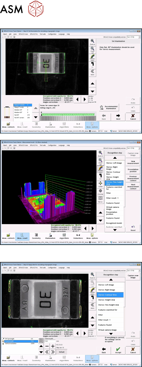
► With the Set illumination option you may check
the illumination setting.
Normally, the pre-set values should not be
changed!
► Under Stereo: Fine Height View you may check
the result of the stereo measurement.
Ensure that the THT pins are in the focal plane
(yellow height line).
This is the case, if component height (overall
height) and nozzle height have been defined cor-
rectly.
Step 5: SIPLACE Vision
► If necessary, change the traverse path to modify
the vertical resolution.
► Under Stereo: Contour lines the measured height
lines are displayed in the 2D images.
This allows you to verify that exactly the THT pin
tips have been detected at the focal plane.
4 Working with the OSC Features
4.2 Stereo Measurement for THT Pins (from R16-2)
Bedienungsanleitung OSC Package User Guide OSC-Paket 11/2018 73
4.2.3 Stereo Measurement for Gullwings and Pattern Features (from R18-2)
From R18-2, the stereo measurement is also supported for the Gullwing and Pattern Features lead
group types. The same procedure is used for the measurement as for the stereo measurement of
THT pins.
NOTICE
Considering the height measuring range
Since Gullwings are often not in the same plane as the THT pin tips, the height measuring
range must be considered:
SST25: +1.94 mm to -3.9 mm around the calibration plane ("+" is in the direction of the
camera !)
SST33: +3.6 mm to -7.2 mm around the calibration plane.
► Follow the work steps that are described in section 4.2 "Stereo Measurement for THT Pins
(from R16-2)" [}67].
► Please also refer to section 4.3 "Customer-specific Pattern Features (from R16-2)" [}75].
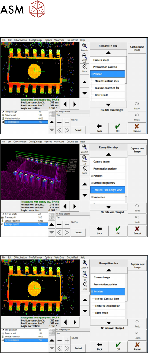
4.2.4 Stereo Measurement – Measurement Parameter 4x Image Capture (from
R18-2)
From R18-2, the 4x image capture measurement parameter can be used in the stereo measure-
ment. At each position four images are then taken, each offset in the X and Y directions by a half
pixel to each other. As a result, features which are smaller than the specified minimum size can be
recognized. The height measuring range is halved with the 4x image capture: with the SST 33, only
the height range from 1.8 mm to -3.6 mm is measured.
Example
4x image capture
Additionally, the traverse path can be shortened to reduce the lighting differences of the images.
Please also refer to section 6.1 "Stereo Measurement for THT Pins" [}99].
► Follow the work steps that are described in section 4.2 "Stereo Measurement for THT Pins
(from R16-2)" [}67]cont., with the following exceptions:
4 Working with the OSC Features
4.2 Stereo Measurement for THT Pins (from R16-2)
74 Bedienungsanleitung OSC Package User Guide OSC-Paket 11/2018
Step 4: SIPLACE Vision
► First, enable the stereo measurement as de-
scribed for the THT pins.
► Then activate the 4x image capture parameter
under Position.
► If necessary, check the result of the
stereo measurement under Stereo: Fine Height
View.
Step 5: SIPLACE Vision
► Check the evaluation of the position in the recog-
nition steps Position and Inspection.
► If necessary, change the traverse path before
you confirm the result of the stereo measure-
ment.