00198374-02_UG_OSC-Paket_R18-2_DE_EN.pdf - 第93页
4 Working with the OSC Features 4.8 Placement of An Exceptionally High Component (fromR18-2) Bedienungsanleitung OSC Package User Guide OSC-Paket 11/2018 93 4.8 Placement of An Exceptionally High Component (fromR18-2) …
4 Working with the OSC Features
4.7 Automatic Illumination Optimization (from R18-2)
92 Bedienungsanleitung OSC Package User Guide OSC-Paket 11/2018
4.7.1 Application Example
The preceding steps in SIPLACE Pro, station software and SIPLACE Vision are assumed.
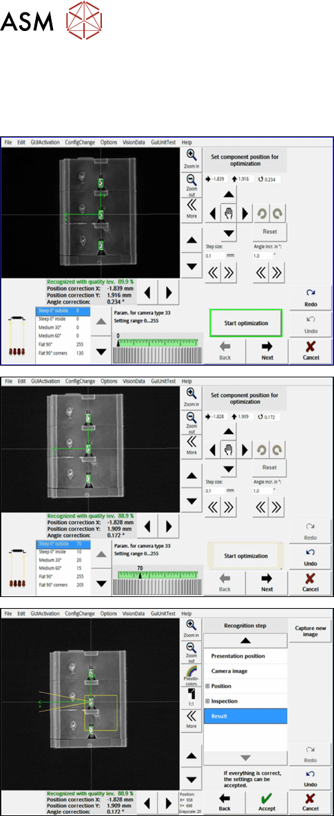
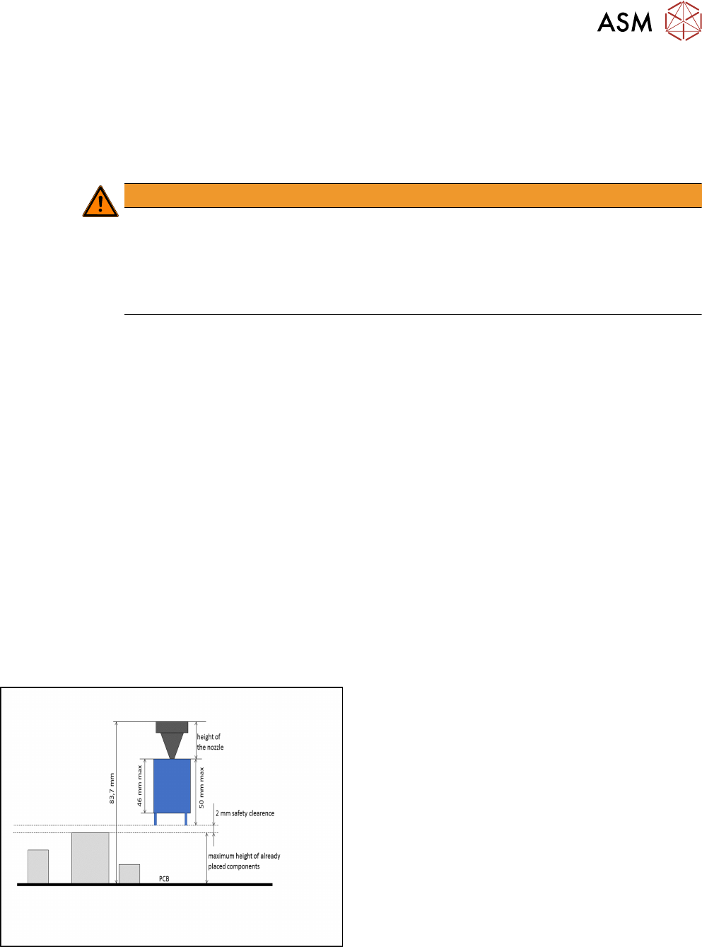
Step 1: SIPLACE Vision
► Important: If the component position could not
be recognized automatically, you must first
manually adjust the position using the arrow and
rotation buttons on the top right.
► Click on the Start optimization button in the Set
component position for optimization dialog.
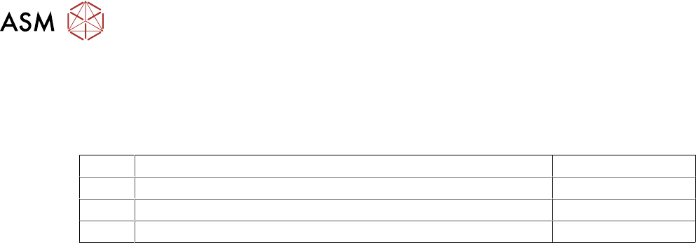
► In the next dialog, click on Next.
► In the next dialog, click on Accept to accept the
result.
During the optimization, the different illumination planes are simulated and images are displayed
continuously with the current best setting. At the end of the optimization, the measurement is per-
formed with the best illumination setting.
4 Working with the OSC Features
4.8 Placement of An Exceptionally High Component (fromR18-2)
Bedienungsanleitung OSC Package User Guide OSC-Paket 11/2018 93
4.8 Placement of An Exceptionally High Component
(fromR18-2)
In a special use case, an exceptionally high component can be placed with automatic crash avoid-
ance by the software. In this case, the gantry and the placement head are moved around this
component. The component must be feeded by a third party feeder module.
WARNING
Description of the component height
It is essential that the description of the component height in SIPLACE Pro is correct.
Otherwise, the hardware (machine, board camera etc.) could be damaged ).
The described component height is used in the station software to decide whether the
placement head and the board camera are allowed to be moved over an already placed
component. If this is not possible without collision, they are moved around this component.
In SIPLACE Pro, a specially defined comment must be created and confirmed for the component
shape. In this case, no height check will be performed, and the component can be placed by a
Twin VHF in the last placement area of the line. The placement positions of this component are the
last ones to be placed.
Prerequisites
●
Placement machine SIPLACE SX V2
●
Single conveyor
●
Placement head Twin VHF, as the only placement head in the station or in combination with
either another Twin VHF or a CPP mounted in high position
●
One component of type SMT; height: max. 46 mm
or
One component of type THT (e.g. Connector or Inductance); height: max. 46 mm without pro-
truding elements which disappear into the board after placement (e.g. centering pins), 50 mm
with protruding elements
●
None of the previously placed components may be higher than the bottom of the exceptionally
high component when it is attached to the placement head after pickup. When using a nozzle
of 20 mm length for placing the exceptionally high component, the previous placed
components are allowed to be 22 mm high. When using a nozzle of 10 mm length, the previ-
ous placed components are allowed to be 32 mm high.
Exceptionally high component
4 Working with the OSC Features
4.8 Placement of An Exceptionally High Component (fromR18-2)
94 Bedienungsanleitung OSC Package User Guide OSC-Paket 11/2018
4.8.1 Procedure
The following overview lists the single work steps that have to be performed in the specified order
to place an exceptionally high component.
Placing an exceptionally high component
Step Action SIPLACE program
1) Enabling OSC package SIPLACE Pro
2) Creating the comment for the component shape SIPLACE Pro
3) Confirming the comment SIPLACE Pro