00198374-02_UG_OSC-Paket_R18-2_DE_EN.pdf - 第63页
4 Working with the OSC Features 4.1 Placement of Snap-In Components (from R16-2) Bedienungsanleitung OSC Package User Guide OSC-Paket 11/2018 63 4.1.1 Procedure The following overview lists the single work steps that hav…

4 Working with the OSC Features
4.1 Placement of Snap-In Components (from R16-2)
62 Bedienungsanleitung OSC Package User Guide OSC-Paket 11/2018
After the first board has been completely produced, it will be transferred to the output section or the
configured inspection station and marked for manual inspection. The operator has to inspect every
snap-in placement position and confirm whether the placement is correct or not. If correct, the cor-
responding Z-axis position will be stored as reference position and used as placement position for
all subsequent boards. If not correct, the measured height will be ignored and the operator must
confirm it again for the next board. The snap-in check is active now. If the Z-axis position deviates
more than the snap-in threshold value from the reference position in a subsequent placement, an
error is reported.
The height reference values are not uploaded to SIPLACE Pro. Thus, when the job is changed at
the placement machine or the machine is shut down, the height reference values have to be taught
again.
NOTICE
Using SIPLACE Smart Pin Support
For reliable snap-in detection it is recommended to set support pins close to the snap-in
placement positions. Detailed information on Smart Pin Support can be found in the
SIPLACE Smart Pin Support Operation and Configuration User Manual, item no.
[00197001-xx].

4 Working with the OSC Features
4.1 Placement of Snap-In Components (from R16-2)
Bedienungsanleitung OSC Package User Guide OSC-Paket 11/2018 63
4.1.1 Procedure
The following overview lists the single work steps that have to be performed in the specified order
to place snap-in components.
Placement of Snap-In Components
Step Action SIPLACE program
1) Enabling OSC package SIPLACE Pro
2) Selecting the snap-in placement process for the component
shape
SIPLACE Pro
3) Enabling the snap-in detection SIPLACE Pro
4) Setting Z-threshold (Default: 0.500 mm) SIPLACE Pro
5) If necessary, configuring the inspection station (Default:
Output section)
Station Software
6) Verifying and confirming all placement positions at the inspec-
tion station
Station Software
4 Working with the OSC Features
4.1 Placement of Snap-In Components (from R16-2)
64 Bedienungsanleitung OSC Package User Guide OSC-Paket 11/2018
4.1.2 Application Example
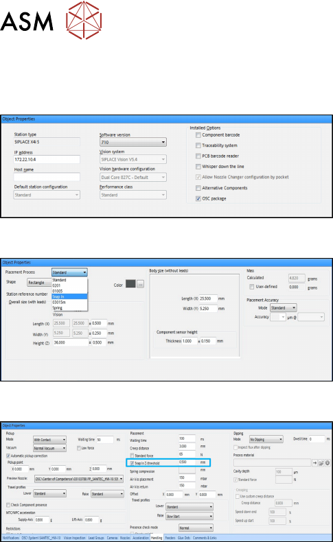
Step 1: SIPLACE Pro
► In the Station Editor under Placement Station,
enable the OSC Package option under Installed
options.
Step 2: SIPLACE Pro
► In the Component Shape Editor, select the Snap
In feature as placement process for the compo-
nent shape.
Step 3 and Step 4: SIPLACE Pro
► In the Handling tab, enable the Snap In Z-
threshold option in the Placement group for the
component shape.
► Define a Z-threshold value in mm.
The threshold value must be > 0.
Default value: 0.500 mm
The first board has to be inspected and confirmed as described in Step 5 and Step 6 below. After
this, the machine uses the Z-threshold value to determine whether the snap-in component is com-
pletely locked in the subsequent boards or not.
Setting Z-threshold value
The Z-threshold value is used to evaluate whether the snap-in component is locked or not. The cur-
rent Z-axis position of every snap-in placement will be compared with its corresponding height ref-
erence position. If the difference between the two values is <= the set Z-threshold value in
SIPLACE Pro, the snap-in component is considered to be locked. If the difference is greater, the
snap-in component is considered not to be locked and an error message is displayed.
If the Z-value is too large, the machine can not detect an erroneous locking. If the Z-threshold value
is too small, the machine may stop often.
Depending on the component, you can start with the default value of 0.500 mm for the Z-threshold
and change this value successively in small steps.