00198374-02_UG_OSC-Paket_R18-2_DE_EN.pdf - 第81页
4 Working with the OSC Features 4.4 Special Position Evaluation (from R16-2) Bedienungsanleitung OSC Package User Guide OSC-Paket 11/2018 81 4.4.2 Application Example Step 1: SIPLACE Pro ► In the Station Editor under Pla…

4 Working with the OSC Features
4.4 Special Position Evaluation (from R16-2)
80 Bedienungsanleitung OSC Package User Guide OSC-Paket 11/2018
4.4.1 Procedure
The following overview lists the single work steps that have to be performed in the specified order
to perform the special position evaluation.
Performing position evaluation
Step Action SIPLACE program
1) Enabling OSC package SIPLACE Pro
2) Defining the alignment for the first group (Default) SIPLACE Vision
3) Defining alignment for the second group (None) SIPLACE Vision
4 Working with the OSC Features
4.4 Special Position Evaluation (from R16-2)
Bedienungsanleitung OSC Package User Guide OSC-Paket 11/2018 81
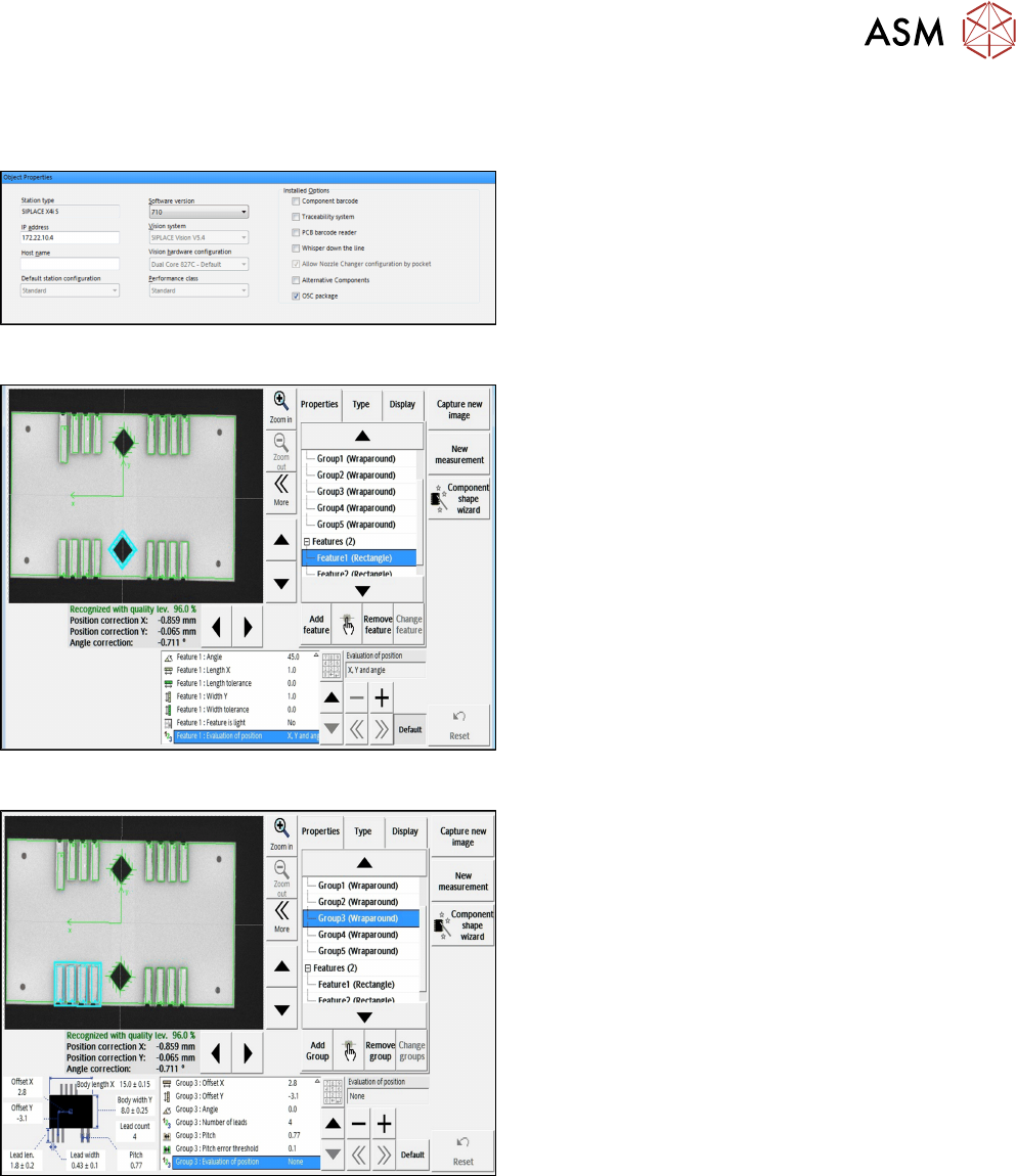
4.4.2 Application Example
Step 1: SIPLACE Pro
► In the Station Editor under Placement Station,
enable the OSC Package option under Installed
options.
Step 2: SIPLACE Vision
► Define the alignment of the two Rectangle
features in the Geometry data under
Evaluationofposition.
In this example: Default (X, Y, angle for
"Rectangle" feature).
Step 3: SIPLACE Vision
► Define the alignment of all Wraparound groups in
the Geometry data under
Evaluationofposition.
In this example:
None for "Wraparound" feature.
All features are searched for and inspected during the measurement. Therefore, all features have
to be available and set correctly. Only in the last step, the position of these features is taken into
account in the calculation of the component position. In the example above, only the positions of
the two rectangle features are used for the calculated component position.

4 Working with the OSC Features
4.5 Finding Best Acceleration (from R16-2)
82 Bedienungsanleitung OSC Package User Guide OSC-Paket 11/2018
4.5 Finding Best Acceleration (from R16-2)
Especially for odd shape components but also for standard components users often reduce the ac-
celeration of the axis to a low value just to ensure that the board is placed correctly and no com-
ponents are lost. However, by that the current acceleration is usually below the optimum.
A new teaching function supports finding the optimal acceleration or speed values for a component
shape directly at the station. The dialog for teaching component shapes has been enhanced by the
new Teach acceleration values function.
The selected component is picked up with the selected nozzle and moved around within the
machine with increasing acceleration values for each axis. Based on the Vision measurement, the
optimal acceleration is determined. The value can be tested again and after testing uploaded to
SIPLACE Pro.
Prerequisites
Activity level: Machine service