00198374-02_UG_OSC-Paket_R18-2_DE_EN.pdf - 第86页
4 Working with the OSC Features 4.5 Finding Best Acceleration (from R16-2) 86 Bedienungsanleitung OSC Package User Guide OSC-Paket 11/2018 Step 6: Station software ► Set the recommended acceleration values from the teach…
4 Working with the OSC Features
4.5 Finding Best Acceleration (from R16-2)
Bedienungsanleitung OSC Package User Guide OSC-Paket 11/2018 85
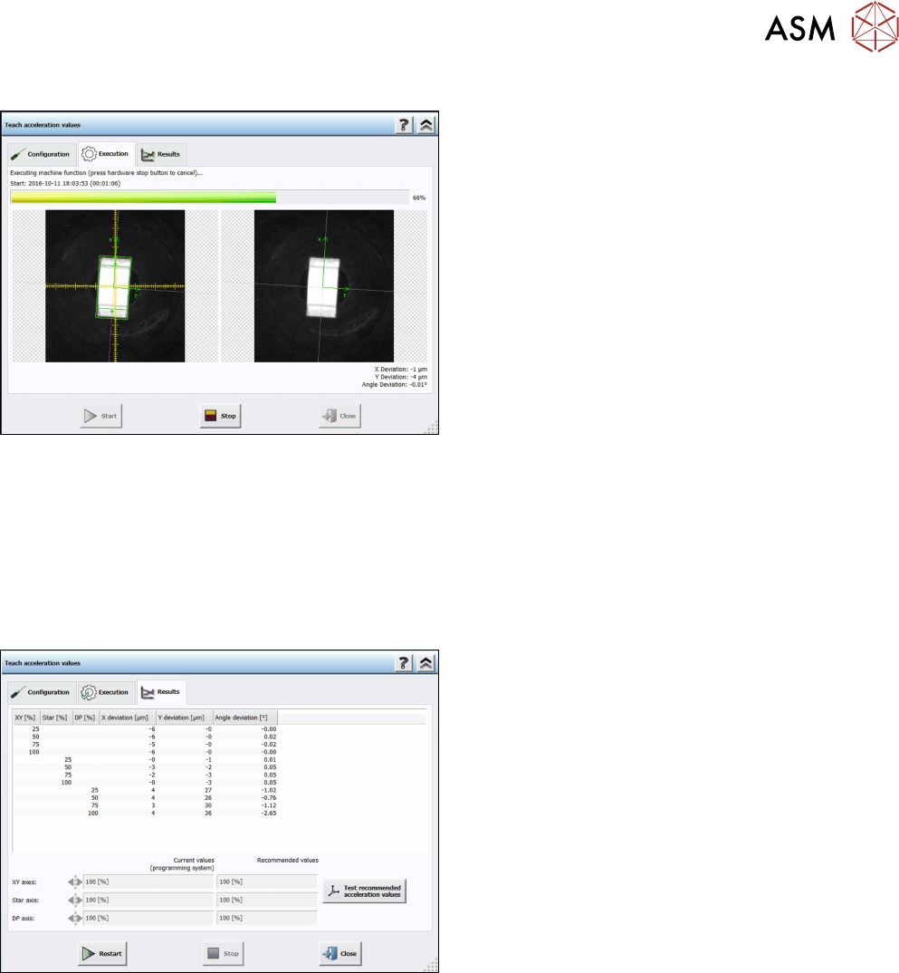
Step 4: Station software
The execution steps are displayed together with the reference Vision image and the last Vision
image done by the camera. Additionally, the current acceleration values of the axes and the
measured deviations are displayed. If you have to remove a component from the placement head
manually or if the component is lost, a hint will be displayed and you must confirm the action to
continue.
If an error occurs during execution, the error causes are displayed on the last page in an error list.
Otherwise, the results are displayed in the Results dialog.
Step 5: Station software
► Check the results. The recommended values can
be compared with the values of the programming
system.
► Click on Test recommended acceleration values
to test the values.
The teach dialog is closed and the Configuration test dialog is opened.
4 Working with the OSC Features
4.5 Finding Best Acceleration (from R16-2)
86 Bedienungsanleitung OSC Package User Guide OSC-Paket 11/2018
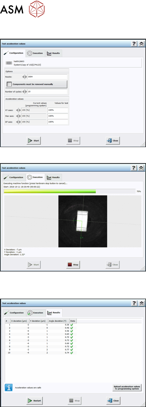
Step 6: Station software
► Set the recommended acceleration values from
the teach function.
► Click on Start.
The test is automatically performed and the Execution test dialog displayed.
The results are displayed in the Results test dialog.
Step 7: Station software
► Check the results.
► Click on Upload acceleration values to program-
ming system.
The upload to SIPLACE Pro is not available until the recommended values have been tested.

4 Working with the OSC Features
4.6 Placement of Components with Centering Pins – PininPaste Height Check (from R18-2)
Bedienungsanleitung OSC Package User Guide OSC-Paket 11/2018 87
4.6 Placement of Components with Centering Pins –
PininPaste Height Check (from R18-2)
When placing components with centering pins, it must be ensured that the centering pins fit into the
corresponding holes on the board. The same procedure is used for the verification as for the place-
ment of snap-in components, but with less placement force.