00198374-02_UG_OSC-Paket_R18-2_DE_EN.pdf - 第74页
4 Working with the OSC Features 4.2 Stereo Measurement for THT Pins (from R16-2) 74 Bedienungsanleitung OSC Package User Guide OSC-Paket 11/2018 Step 4: SIPLACE Vision ► First, enable the stereo measurement as de- scribe…
4 Working with the OSC Features
4.2 Stereo Measurement for THT Pins (from R16-2)
Bedienungsanleitung OSC Package User Guide OSC-Paket 11/2018 73
4.2.3 Stereo Measurement for Gullwings and Pattern Features (from R18-2)
From R18-2, the stereo measurement is also supported for the Gullwing and Pattern Features lead
group types. The same procedure is used for the measurement as for the stereo measurement of
THT pins.
NOTICE
Considering the height measuring range
Since Gullwings are often not in the same plane as the THT pin tips, the height measuring
range must be considered:
SST25: +1.94 mm to -3.9 mm around the calibration plane ("+" is in the direction of the
camera !)
SST33: +3.6 mm to -7.2 mm around the calibration plane.
► Follow the work steps that are described in section 4.2 "Stereo Measurement for THT Pins
(from R16-2)" [}67].
► Please also refer to section 4.3 "Customer-specific Pattern Features (from R16-2)" [}75].
4.2.4 Stereo Measurement – Measurement Parameter 4x Image Capture (from
R18-2)
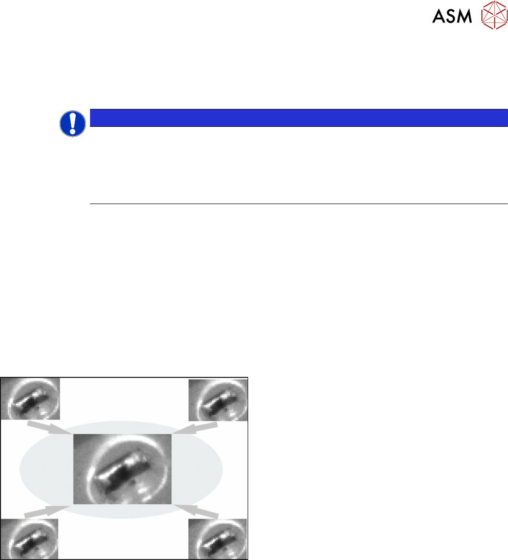
From R18-2, the 4x image capture measurement parameter can be used in the stereo measure-
ment. At each position four images are then taken, each offset in the X and Y directions by a half
pixel to each other. As a result, features which are smaller than the specified minimum size can be
recognized. The height measuring range is halved with the 4x image capture: with the SST 33, only
the height range from 1.8 mm to -3.6 mm is measured.
Example
4x image capture
Additionally, the traverse path can be shortened to reduce the lighting differences of the images.
Please also refer to section 6.1 "Stereo Measurement for THT Pins" [}99].
► Follow the work steps that are described in section 4.2 "Stereo Measurement for THT Pins
(from R16-2)" [}67]cont., with the following exceptions:
4 Working with the OSC Features
4.2 Stereo Measurement for THT Pins (from R16-2)
74 Bedienungsanleitung OSC Package User Guide OSC-Paket 11/2018
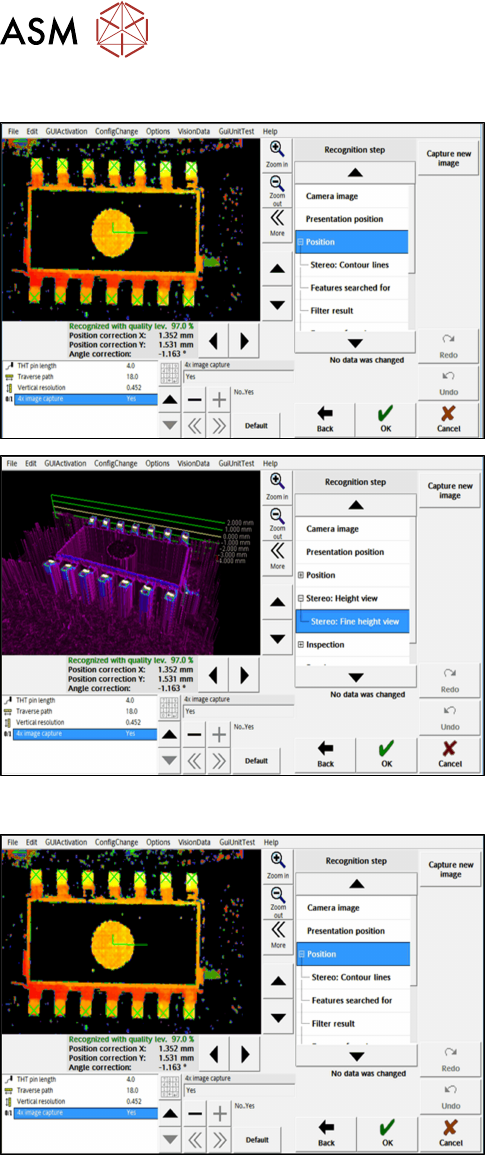
Step 4: SIPLACE Vision
► First, enable the stereo measurement as de-
scribed for the THT pins.
► Then activate the 4x image capture parameter
under Position.
► If necessary, check the result of the
stereo measurement under Stereo: Fine Height
View.
Step 5: SIPLACE Vision
► Check the evaluation of the position in the recog-
nition steps Position and Inspection.
► If necessary, change the traverse path before
you confirm the result of the stereo measure-
ment.
4 Working with the OSC Features
4.3 Customer-specific Pattern Features (from R16-2)
Bedienungsanleitung OSC Package User Guide OSC-Paket 11/2018 75
4.3 Customer-specific Pattern Features (from R16-2)
Odd shape components do not always have a shape or other structures such as leads which can
be used for identifying the component center and its orientation.
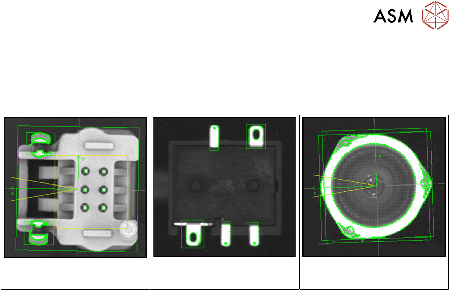
Examples
Component with board locks Specially shaped leads Component with curved shape,
e.g. lenses
The Pattern Feature lead group type allows the user to describe arbitrary abstract patterns on a
component. These patterns can only be created and changed in the SIPLACE Vision Editor during
teaching at the station. This type of lead group can be renamed or deleted but not created, edited
or copied in SIPLACE Pro.
The camera captures an image of the component and the user can now simply draw a frame
around single features or attributes and mark them for the Vision system. A special algorithm will
then extract a model out of the marked areas which can be used to later measure and align all
components of the same type. Structures that are not needed can be deleted easily.