CP6的IO代码.pdf - 第137页
Part 3 Chapter 3 Replacing Consumable Parts Edition 1.1 3-3-8 CP-6-series Mechanical Reference The vacuum pump construction and names of each component are shown below. (a) Motor 0.75KW, 4P (b) Vacuum pump KH750A (c) Bel…
Part 3 Chapter 3 Replacing Consumable Parts
Edition 1.1 3-3-7 CP-6-series Mechanical Reference
3.6 Replacing Vacuum Pump Parts
Point
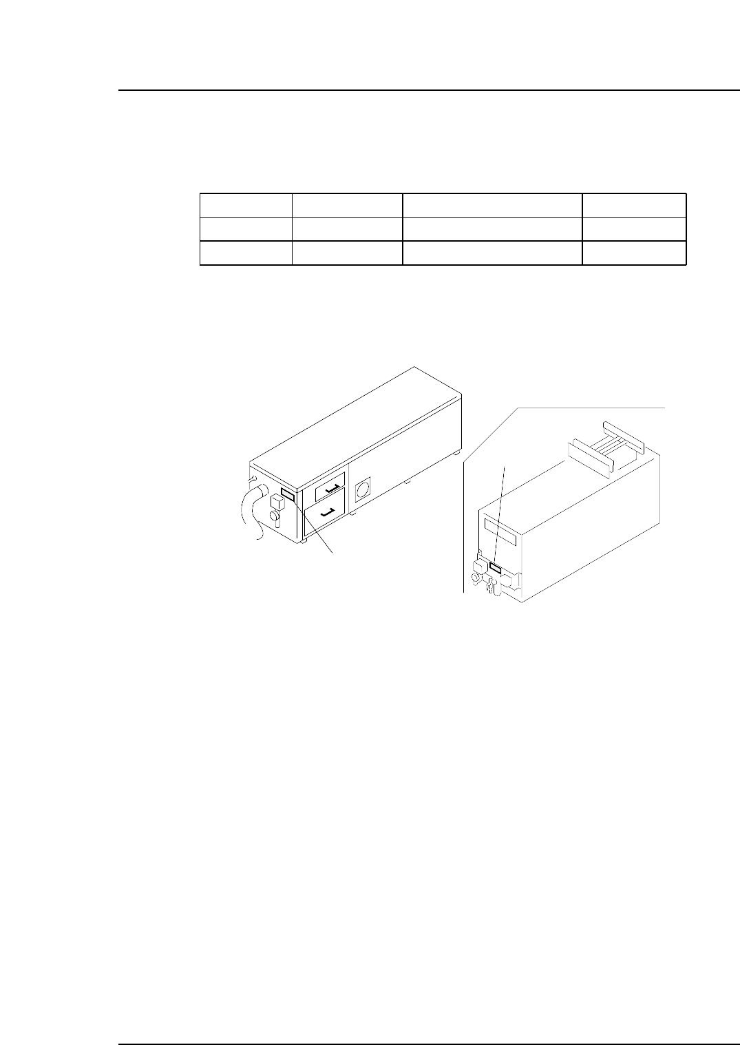
The following types of vacuum pumps are used.
When the new type of vacuum pump is used, the maker's seal can be found on the side
noise reduction box.
Sticker
Sticker
CP6M3062
CP-652C
Name
Vacuum pump
Vacuum pump
Machine type
Except CP-652C
CP-652C
No.
KH750A-302-G1
KHA750A-302-G1
Noise reduction box ASSY No.
AMPZ-9410
AYPV-9300
CP6M3061
Part 3 Chapter 3 Replacing Consumable Parts
Edition 1.1 3-3-8 CP-6-series Mechanical Reference
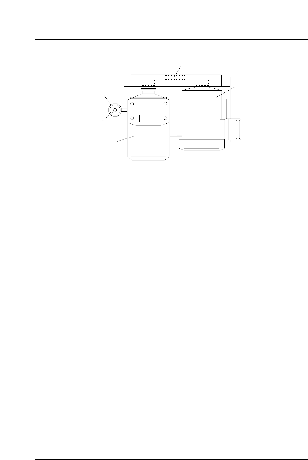
The vacuum pump construction and names of each component are shown below.
(a) Motor 0.75KW, 4P
(b) Vacuum pump KH750A
(c) Belt Polymax belt, 7M-670
(d) Filter 750A
(e) Filter element No. 04A30159010
(a)
(c)
(b)
(d)
(e)
CP6M3063
Part 3 Chapter 3 Replacing Consumable Parts
Edition 1.1 3-3-9 CP-6-series Mechanical Reference
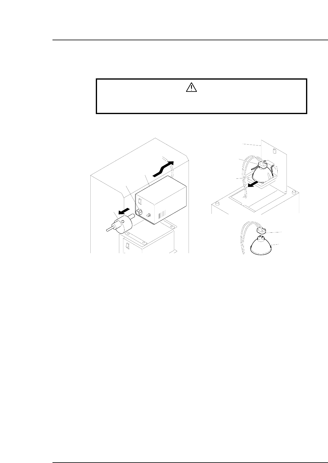
3.7 Replacing the Vision Processing Halogen Lamp
Procedure
Warning
Always be sure to cut out the 200 V power before carrying out any
work.
1. Loosen the screw which secures the shutter to the light source unit, then detach
the shutter from the light source unit.
2. While supporting the light source unit, push it toward the rear of the machine to
extract it.
Note: If the light source cannot be extracted, use scissors, etc., to cut the tie-band which
secures the wires, being careful not to harm the wires.
3. After extracting the light source unit, turn it upside down and lift the latch to open
the cover.
4. Pull out the halogen lamp together with the socket.
5. Unplug the lamp from the socket, and plug in the new lamp.
Note: Avoid touching the lamp glass with your hands. Fingerprints, etc., on the lamp glass
can shorten its life.
6. Re-install the light source unit by reversing the above procedure.
Notes:
1. After returning the light source unit to its original position, be sure that the wiring is
not protruding toward the rear of the machine as it could catch on a feeder during
device table motion. To prevent this, push the wiring into the space between the
light source unit and the mounting face.
2. If the wiring tie-band was cut, attach a new tie-band.
CP6M3064E
Shutter
Screw
Light source unit
Socket
Socket
Cover
Halogen lamp
Halogen lamp