CP6的IO代码.pdf - 第224页
Part 5 Chapter 5 Servo Adjustments Edition 1.0 5-5-1 CP-6 Series Mechanical Reference 5. The Servo System The servo system is responsible for the motions of the machine. This system carries the board(s) to the correct pl…

Notes:
Part 5 Chapter 4 Engagement Rail Adjustments
Edition 1.0 5-4-4 CP-6 Series Mechanical Reference
Part 5 Chapter 5 Servo Adjustments
Edition 1.0 5-5-1 CP-6 Series Mechanical Reference
5. The Servo System
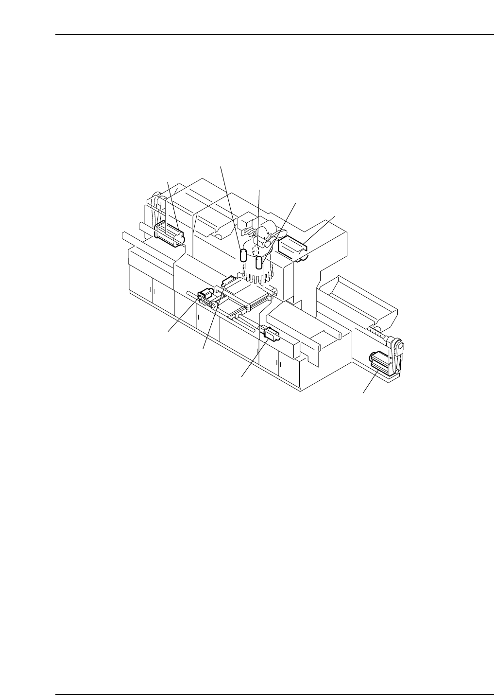
The servo system is responsible for the motions of the machine. This system carries the board(s) to
the correct placing position, carries the tape feeders to the component pick-up point, rotates the cam
turret, changes nozzle sizes, and also accurately rotates components to the desired placing angle.
The following section details the individual components of the loading position and the step-by-step
procedure for adjustments vital to maintaining this system.
Y-axis motor
D2-axis servo motor
Fine θ-axis motor
Fine θ reverse-axis motor
Nozzle change NC-axis motor
Cam-axis motor
Z-axis motor
X-axis motor
D1-axis servo motor
CP6M5074
Part 5 Chapter 5 Servo Adjustments
Edition 1.0 5-5-2 CP-6 Series Mechanical Reference
5.1 Servo System Components
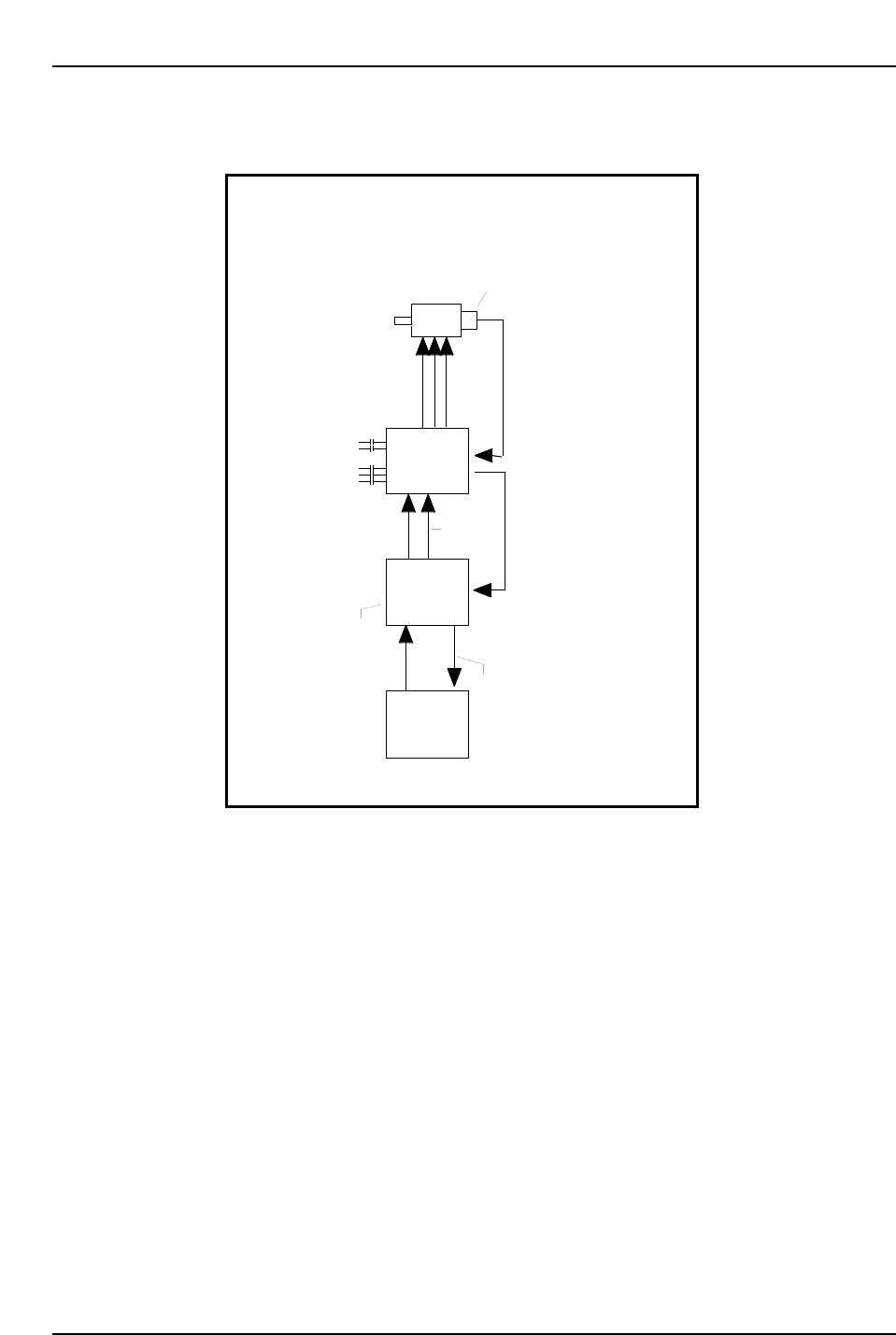
A simplified illustration of the CP-6 series servo system is shown below.
CP6M5075
The servo system for the FCP-6 is a semi closed-loop system. The system consists of the
CPU and Servo boards, servo amplifiers, servo motors and servo motor encoders. The
semi closed loop configuration is achieved through the encoder-to-amplifier connection.
The machine uses the constant stream of positional data from the encoder to alter the
position of the motor. This allows the machine to keep a very tight placement tolerance
and a high rate of repeatability.
HMIV-134 CPU Board
The CPU board controls all functional decisions undertaken at the machine. This card is
responsible for the initiation of all servo axis motions.
IS70B Servo Boards
There are three servo driver cards in the VME card rack and these cards interface the
CPU board to the servo amplifiers. The first card controls the CAM, FRQ- and Z-axis.
The second card controls the X-, Y- and FQ-axis. The third card controls the D1-, D2- and
NC-axis. The cards take the binary movement data (in pulses) and direction commands
from the CPU board and send analog signals to the servo amplifiers which in turn drive
the motors.
Fundamental Block Diagram of the
FCP-642 Servo System Interface
CPU
HIMV-134
Servo Board
IS70B
Servo
Amplifier
Servo
Motor
Speed Feedback Loop
Binary Data
Final Positioning Data
Speed
Command
Input
IN-B
SGB
Converts Digital to Analog
U
V
W
Pulse Generator
or
Encoder
200 VAC.
Control Circuit
Power Input
Main Power
Input
Positioning Feedback Loop
Note: For the X-, Y-axes, the speed command input line uses V-REF instead of IN-B.