CP6的IO代码.pdf - 第232页
Part 5 Chapter 5 Servo Adjustments Edition 1.0 5-5-9 CP-6 Series Mechanical Reference Note: 1. For the X- and Y-axes, adjust using the UHi parameter values first. After adjustment, enter the mid parameter values to ensur…
Part 5 Chapter 5 Servo Adjustments
Edition 1.0 5-5-8 CP-6 Series Mechanical Reference
< D-Axis>
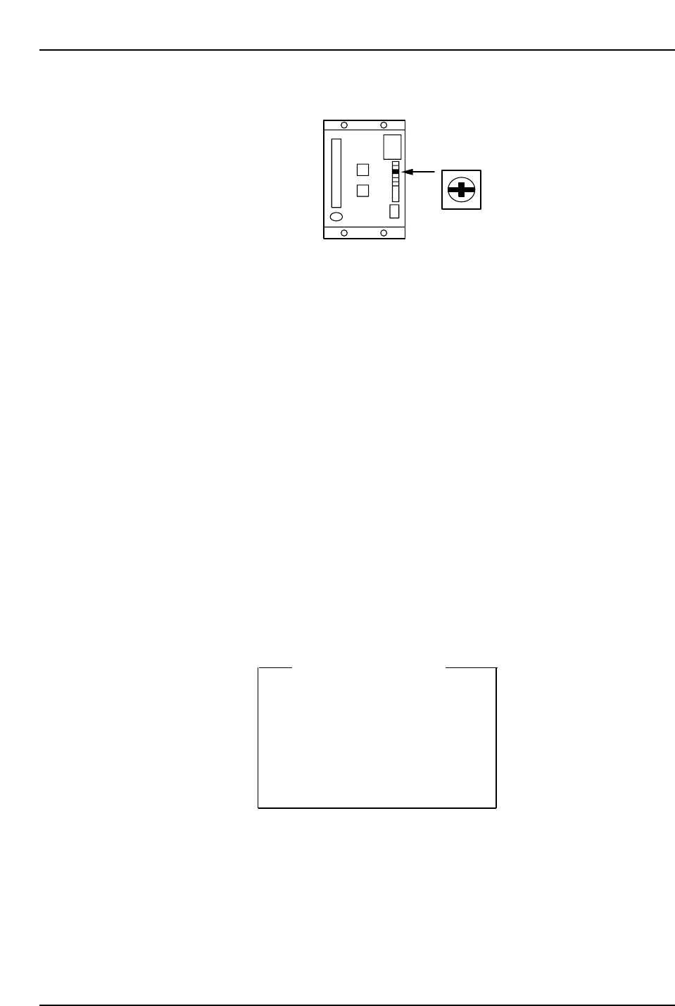
Use the LOOP volume pot to adjust the GAIN on the D-axes (see diagram below).
Note: No feeders should be loaded on the D-table during adjustment.<C-Axis>
[MODE] (sw 4) [C] [n] [-] [0] [0] will be displayed
→ [▲] (sw 2)
→ [C] [n] [-] [0] [4] will be displayed
→ [DATA] (sw 1 + sw 4)
→ [ ] [ ] [4] [0] [0] (loop gain)
→ [DATA] (sw 1 + sw 4)
→ [C] [n] [-] [0] [4]
<X-, Y-, Z-, FQ-, FRQ-, NC -axis>
Connect the Digital Operator to the amp.
[DISP SET]
→ [C] [n] [-] [0] [0] will be displayed
→ [▲]
→ [C] [n] [-] [0] [4] will be displayed
→ [*] [*] [*] [*] [*] (loop gain)
→ [DATA ENTER]
→ [C] [n] [-] [0] [4] will be displayed
Loop Gain Value
X → 80
Y → 95
Z → 120
Fθ → 240
FRθ → 240
NC → 350
CP6M5080
LOOP
CP6M5079
Part 5 Chapter 5 Servo Adjustments
Edition 1.0 5-5-9 CP-6 Series Mechanical Reference
Note: 1. For the X- and Y-axes, adjust using the UHi parameter values first. After adjustment,
enter the mid parameter values to ensure that the travel time and overshoot are as
specified in Table 1 “Max, Travel Time and Overshoot”.
2. For the FQ, FRQ and NC-axes, adjust by using the ROT parameter values. After
adjustment, enter the REV parameter values to ensure that the travel time and overshoot
are as specified in Table 1.
3. For digital input servo amplifiers, use a loop gain value specified in the table above. No
servo adjustment is required.
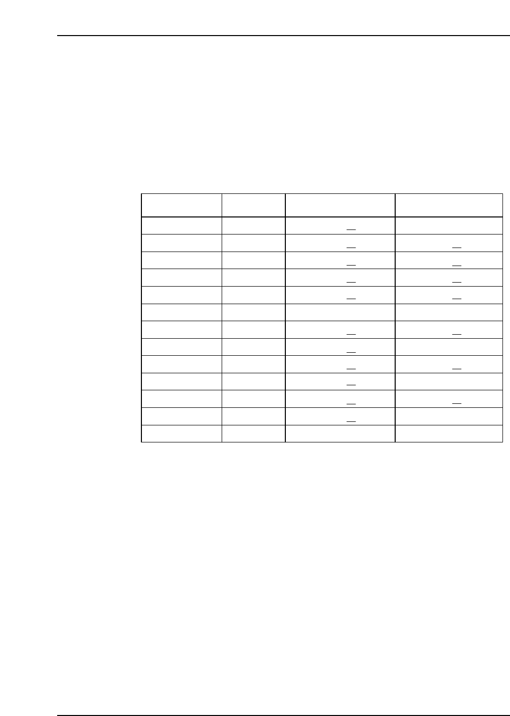
If an axis does not satisfy the specs in table 1, check it again after idling the relevant axis.
Axis Condition Travel time (ms) Max, overshoot (pulse)
X UHi
X Mid
Y UHi
Y Mid
Z
C
D
Fθ ROT
No load
56 ~ 59
✻1
Fθ REV
FRθ ROT
FRθ REV
NC ROT
NC REV
200 degrees
200 degrees
200 degrees
0 degrees
0 degrees
0 degrees
0 ~ 4
0 ~ 4 ✻1
0 ~ 4 ✻1
0 ~ 4 ✻1
0 ~ 5 ✻1
0 ~ 4
2 ~ 4 ✻1
0 ~ 4
0 ~ 4 ✻1
0 ~ 4
0 ~ 4 ✻1
4 ~ 8
0 ~ 4
56 ~ 59
✻1
56 ~ 59 ✻1
56 ~ 59 ✻1
50 ~ 54 ✻1
166 ~ 171
72 ~ 73 ✻1
29 ~ 35 ✻1
29 ~ 35 ✻1
29 ~ 35 ✻ 1
29 ~ 35 ✻1
19 ~ 22 ✻1
31 ~ 33
Table 1 : Max, Travel Time and Overshoot
CP6M5081
Part 5 Chapter 5 Servo Adjustments
Edition 1.0 5-5-10 CP-6 Series Mechanical Reference
5.2.2 CP-643E Servo Adjustments
When performing servo adjustments on the CP642, the machine should be booted up in
“Mechacheck mode”, the boot-up procedure for which is detailed in the section below.
Note: The procedure explained below is valid from ROM versions 305 or later.
Before Starting Adjustments
1) Boot-up the machine in “Mechacheck mode”.
[3] (axis change button) + RESET + POWER ON
Following this, both shutters should be raised to avoid collision with the device
tables.
2) Ensure the cam axis is at 0° and that all stopper solenoids are set to OFF.
3) Specify the axis to be adjusted:
[SERVO] → [+ PAGE], [- PAGE]
4) Prepare axis movement:
[SERVO MOVE]
5) Perform zero-setting.
Zero Adjustment
<D-Axis>
[V_TEST] → [ZERO] → START
The current servo count appears on the screen. The value will fluctuate.
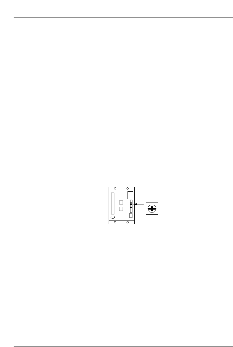
Turn the ZERO volume on the amp slowly to eliminate any fluctuation.
When the counter becomes stable, press CYCLE STOP.
Refer to the figure below for the location of the ZERO volume.
<C and X-Axis>
Connect the digital operator to the servo amplifier, and perform the automatic zero
adjustment and then manual zero adjustment.
[V_TEST] → [ZERO] → START
A changing servo counter value displays on-screen.
Automatic Zero Adjustment
[DSPL SET] → [C][n][-][0][0] displays → [DATA ENTER] → [0][0][-][0][0] displays →
[▲] → [0][0][-][0][1] displays → [DSPL SET]
ZERO
CP6M5082