CP6的IO代码.pdf - 第173页
Part 5 Chapter 2 Cam Box Edition 1.2 5-2-10 CP-6-series Mechanical Reference Notes:
Part 5 Chapter 2 Cam Box
Edition 1.2 5-2-9 CP-6-series Mechanical Reference
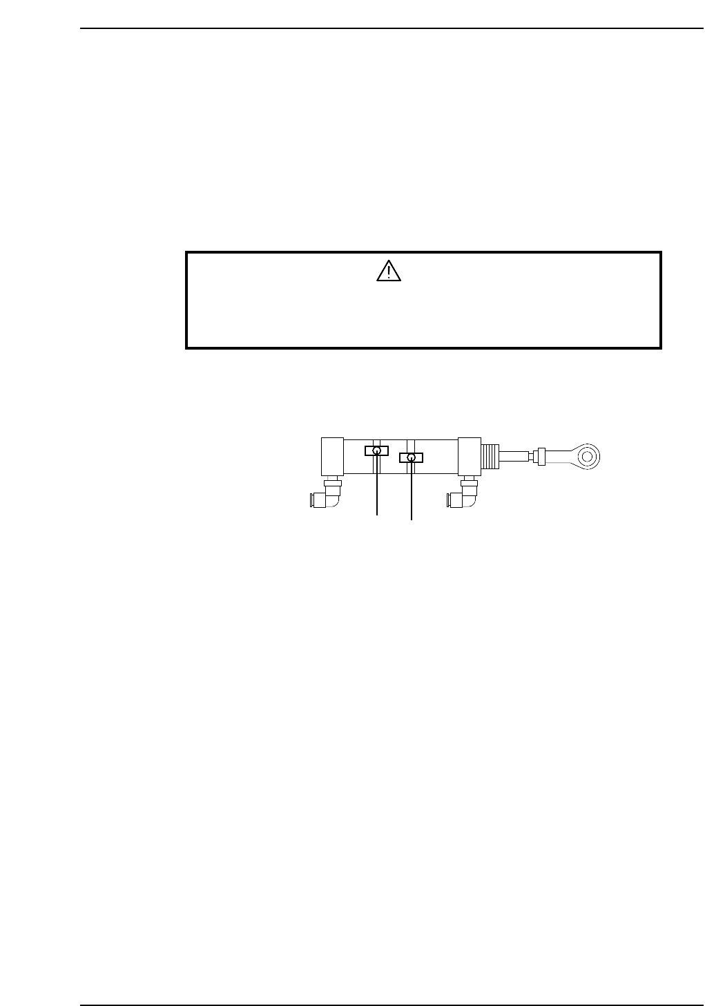
2.5 3rd/13th Station Air Cylinder Sensor Adjustment
The sensors on both cylinders for +90° and -90° should activate the moment either
rotation is complete. Follow the procedure below to adjust the sensor position.
Adjustment Procedure
1. Set the cam angle to 0°.
2. Activate the PQ +90° rotation by switching the I/O (Y024 PQ ROT. 90°) to ON.
3. Adjust the position of the sensor to activate when the cam angle is 210°~212°.
WARNING
Exercise extreme caution when working on the machine if the cam is
not at its origin (0 deg.). Recoil of the cam axis can endanger the
operator.
4. Similarly, to adjust the -90° sensor position, set the cam back to 0° and activate the
PQ -90° rotation by switching the I/O (Y025 PQ ROT. 270°).
5. Adjust the position of the sensor to activate when the cam angle is 210°~212°.
Pretheta air cylinder
-90° rotation
+90° rotation
CP6M5013

Part 5 Chapter 2 Cam Box
Edition 1.2 5-2-10 CP-6-series Mechanical Reference
Notes:
Part 5 Chapter 3 Station Adjustments
Edition 1.0 5-3-1 CP-6 Series Mechanical Reference
3. Station Adjustments
3.1 Station 1
Part Pick-Up
Station 1 is responsible for indexing the tape feeder and picking up parts.
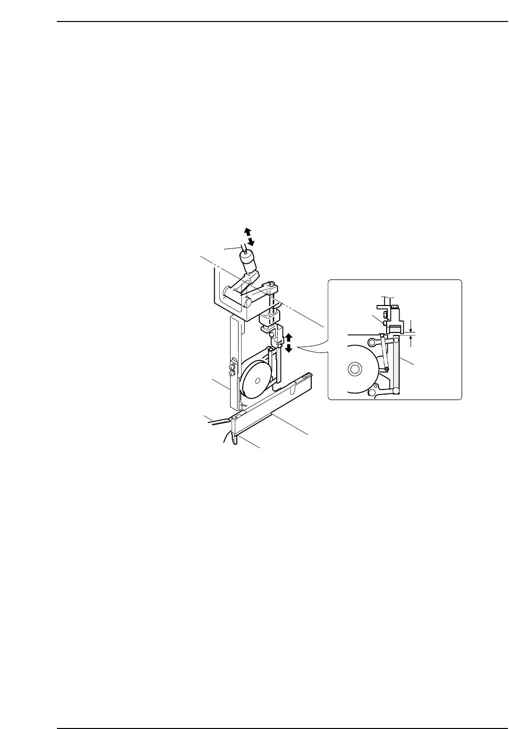
3.1.1 Tape Feed Lever
The pitch lever is the mechanism that advances the feeder tape.
The vertical movement of this lever moves the tape to the pick-up location.
Two types of adjustment (rod and sensor adjustments) are required.
Adjustment rod
Roller
0.5 mm
Tape feed
lever
CP6M5014