CP6的IO代码.pdf - 第178页
Sensor Sensitivity Adjustment 1. Rotate the sensitivity trimmer slowly to the right and ensure that the green LED lights up at the A location. 2. Remove the paper tape from the feeder. The green LED should turn off at th…
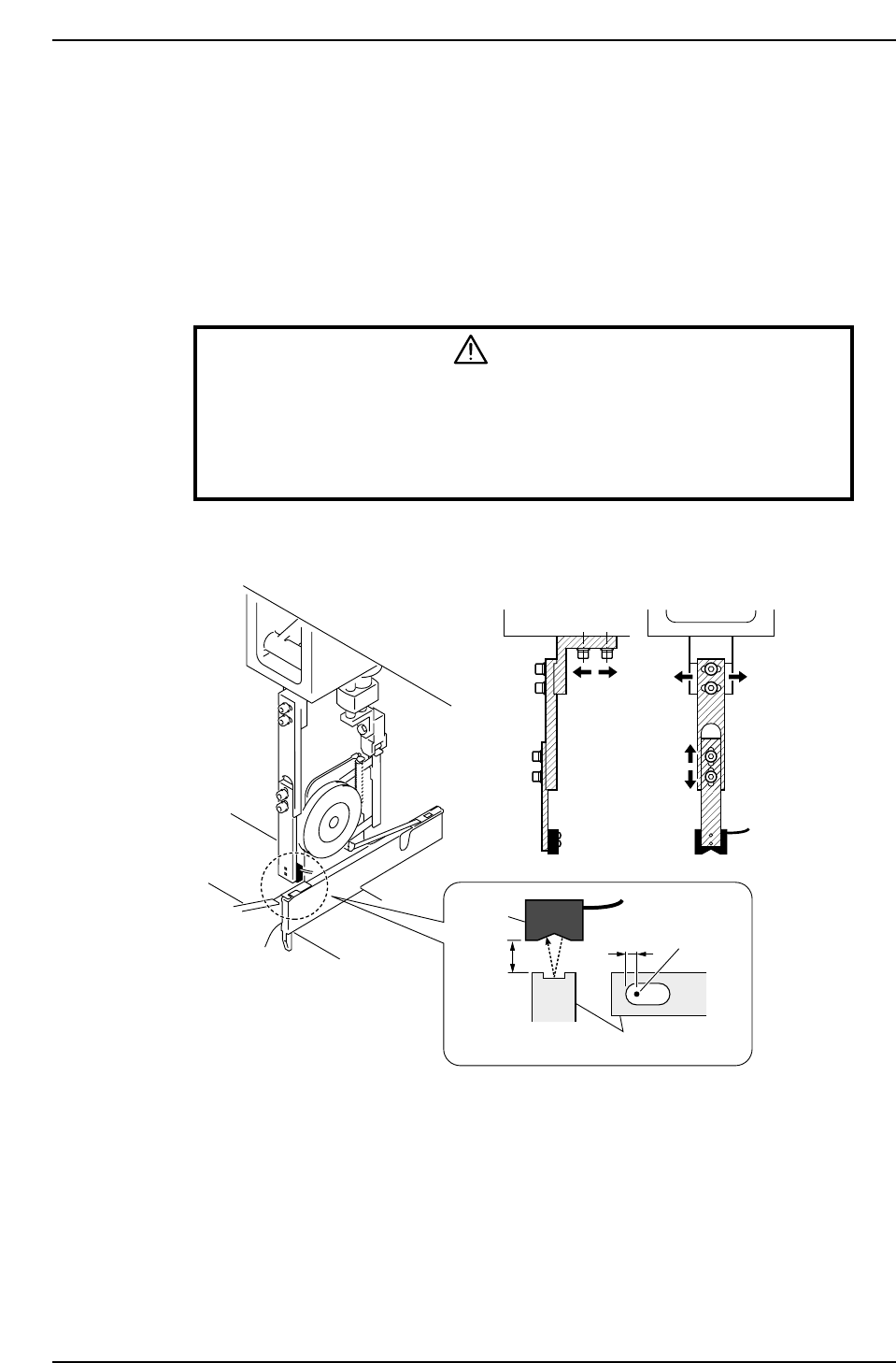
3.1.2 Tape-end Detection
It is possible to know when the tape is about to end due to a reflective sensor that detects
the tape-end.
Sensor Position Adjustment
1. Set an 8 x 4 mm tape feeder in the D1 position.
2. Press [SET] - [D pos] - [1] - [CR] and the START button to move the feeder to
station 1.
3. Press the EMERGENCY STOP button to take the 200 V down to 100 V.
WARNING
• Always be sure to cut off the 200 V power before carrying out any
work.
• Exercise extreme caution when working on the machine if the cam is
not at its origin (0 deg.). Recoil of the cam axis can endanger the
operator.
4. Ensure that the distance between the tape and the sensor is approximately 10 mm.
Sensor
10 ~11mm
2.5 mm
Feeder
Beam
CP6M5018
Part 5 Chapter 3 Station Adjustments
Edition 1.0 5-3-4 CP-6 Series Mechanical Reference
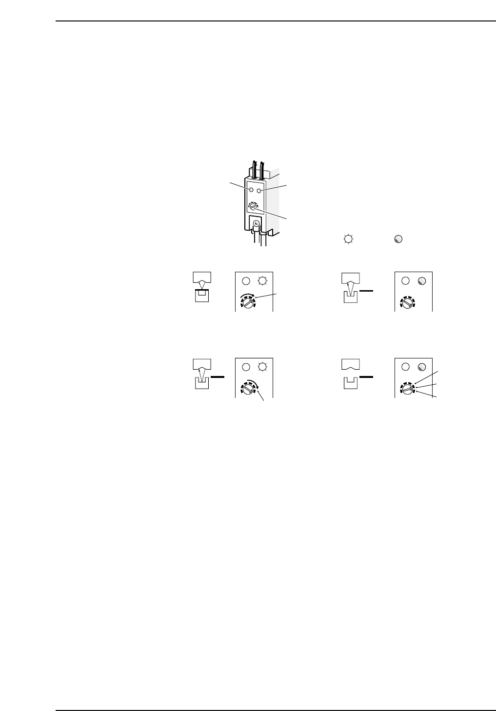
Sensor Sensitivity Adjustment
1. Rotate the sensitivity trimmer slowly to the right and ensure that the green LED
lights up at the A location.
2. Remove the paper tape from the feeder. The green LED should turn off at this
point.
3. Rotate the trimmer slowly to the right again and ensure that the green LED lights
up at the B location.
4. Set the sensitivity trimmer to be between A and B.
5. Ensure that the sensor actually detects the tape-end.
Red LED
Green LED
Trimmer
A
SET
(2)(1)
CP6M5019
B
(4)(3)
A
B
Lit Not lit
Part 5 Chapter 3 Station Adjustments
Edition 1.0 5-3-5 CP-6 Series Mechanical Reference
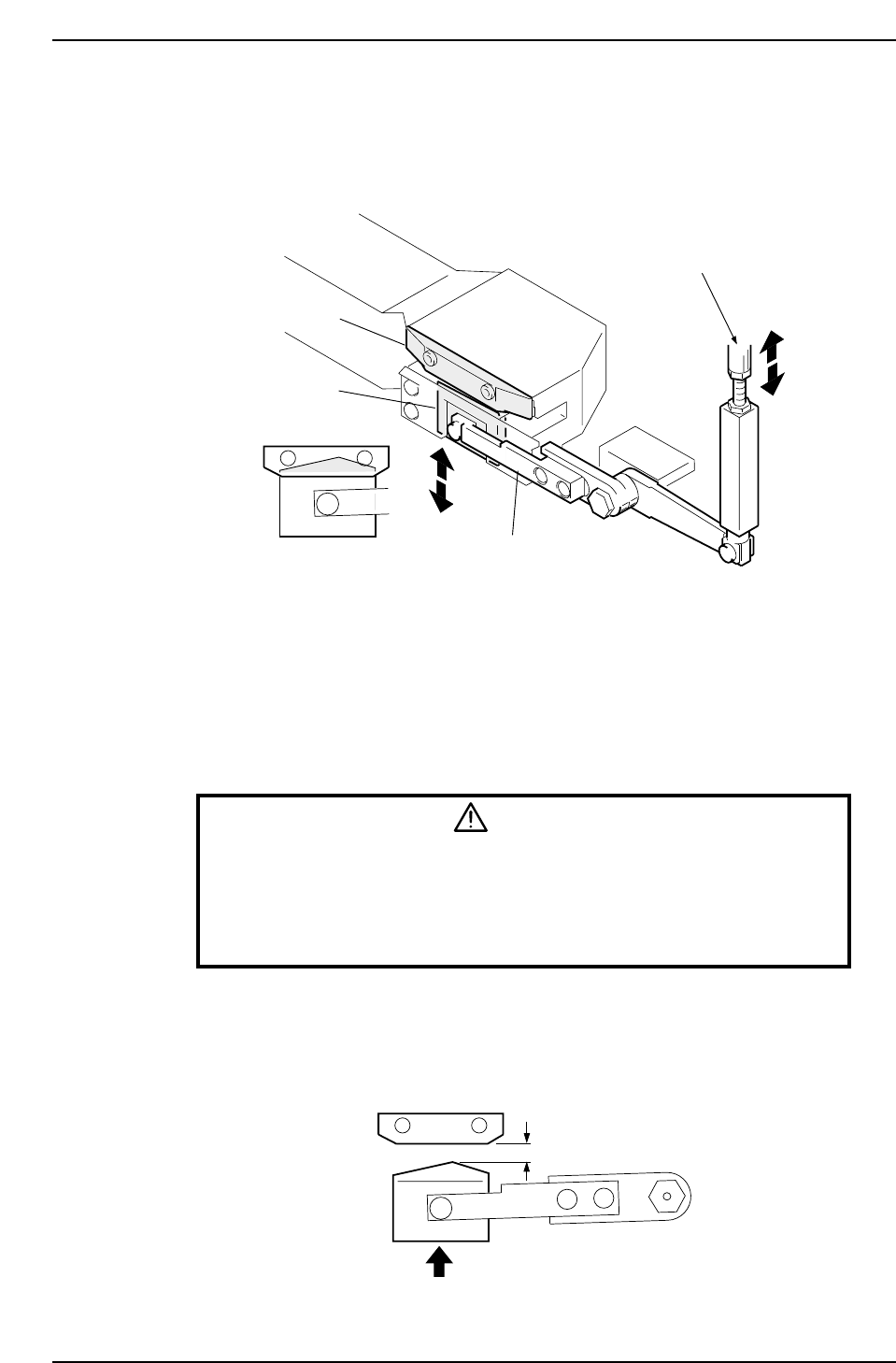
3.1.3 Waste Tape Cutter
• The waste tape cutter cuts tape that protrudes from feeder tips. A vacuum takes the
cut tape into the waste tape box at the back side of the machine.
• Rotate the adjustment rod to align the movable blade with the fixed blade.
Adjustment procedure
<4000 Type>
1. Press the EMERGENCY STOP button. This cuts the 200V servo power and leaves
on only the 100V power supply.
WARNING
• Always be sure to cut off the 200 V power before carrying out any
work.
• Exercise extreme caution when working on the machine if the cam is
not at its origin (0 deg.). Recoil of the cam axis can endanger the
operator.
2. Use the cam handle to rotate the cam to 203°.
3. Adjust the rod so that the fixed blade completely hides the movable blade.
4. There needs to be more than 9 mm between the fixed and movable blades when
the cam is at 0°.
More than 9 mm
CP6M5021
Fixed blade
Movable blade
Cutter lever
Adjustment rod
CP6M5020
Part 5 Chapter 3 Station Adjustments
Edition 1.0 5-3-6 CP-6 Series Mechanical Reference