CP6的IO代码.pdf - 第307页
1.13 Feeder Setting Restrictions Because there are restrictions when setting feeders on the device table, refer to the following tables for limitations. Device T able Edge Restrictions Pitch Requirements between Feeders …
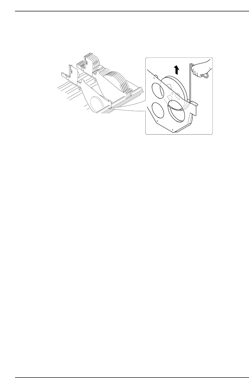
• 7-inch Reel Remover Jig
The 7-inch reel remover jig is useful for removing 7-inch reels set in 13-inch
holders loaded on the device table as shown in the following drawing.
Using the 7-inch Reel Remover Jig
CP6M8068
Part 8 Chapter 1 WC Feeders
Edition 1.0 8-1-44 CP-6 Series Mechanical Reference
1.13 Feeder Setting Restrictions
Because there are restrictions when setting feeders on the device table, refer to the
following tables for limitations.
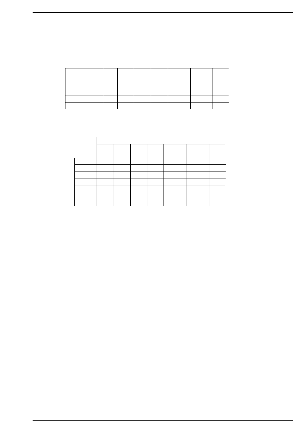
Device Table Edge Restrictions
Pitch Requirements between Feeders
Note : 1. The expressions “Left side” and “Right side” refer to the feeder mounting positions
when viewed from the back of the machine.
2. The numbers in the table (1P, 2P, 3P) refer to the number of device slots required
from the center of one feeder to the center of the next.
3. The numbers in parentheses indicate the number of empty device spaces between
feeders.
W8
W12
W16
W24
W32(J )
W32(E)
W44
W8
1P(0)
2P(1)
2P(1)
2P(1)
3P(2)
2P(1)
3P(2)
W12
2P(1)
2P(1)
2P(1)
2P(1)
3P(2)
3P(2)
3P(2)
W16
2P(1)
2P(1)
2P(1)
2P(1)
3P(2)
3P(2)
3P(2)
W24
2P(1)
2P(1)
2P(1)
3P(2)
3P(2)
3P(2)
3P(2)
Left side
Right side
W32(J)
2P(1)
3P(2)
3P(2)
3P(2)
3P(2)
3P(2)
3P(2)
W32(E)
2P(1)
3P(2)
3P(2)
3P(2)
3P(2)
3P(2)
3P(2)
W44
3P(2)
3P(2)
3P(2)
3P(2)
4P(3)
3P(2)
4P(3)
CP6M8069a
Device No.
D1
D70
D71
D140
W8
✓
✓
✓
✓
W12
X
X
X
X
W16
X
X
X
X
W24
X
X
X
X
W32(J)
X
X
X
X
W32(E)
X
X
X
X
W44
X
X
X
X
CP6M8069
Part 8 Chapter 1 WC Feeders
Edition 1.0 8-1-45 CP-6 Series Mechanical Reference

Table Explanation Example
On the right side of the W16 feeder is a W24 feeder (viewed from the rear).
Table Explanation Example
W24
W16
2 P(1)
Left side
Right side
Left
Right
Feeder pitch 2P
Open slot (1)
CP6M8070
Part 8 Chapter 1 WC Feeders
Edition 1.0 8-1-46 CP-6 Series Mechanical Reference