CP6的IO代码.pdf - 第193页
3.1.8 Bottom Feeder Lift Sensor Adjustment W ARNING Always be sure to cut off the 200 V power before carrying out any work. 1. Set the space between the feeder and the lever to be 0.2 mm. 2. Adjust the sensor height so t…
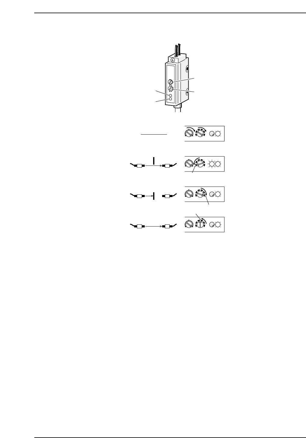
Sensor Sensitivity Adjustment
1. Rotate volumes 1 and 2 all the way to the right.
2. Pass the beam to the receiver. Slowly rotate volume 2 to the left until the red LED
(position A) lights up.
3. Break the light beam with a ruler (or something similar) and slowly rotate volume
2 to the right from (A) until the red LED goes out (position B).
4. Set volume 2 in between (A) and (B).
MAXMIN
+
-
MAXMIN
+
-
MAXMIN
+
-
MAXMIN
+
-
Red LED
Green LED
Volume 1
Volume 2
SET
(1)
(2)
(3)
(4)
(B)
(A)
CP6M5037
Part 5 Chapter 3 Station Adjustments
Edition 1.0 5-3-19 CP-6 Series Mechanical Reference
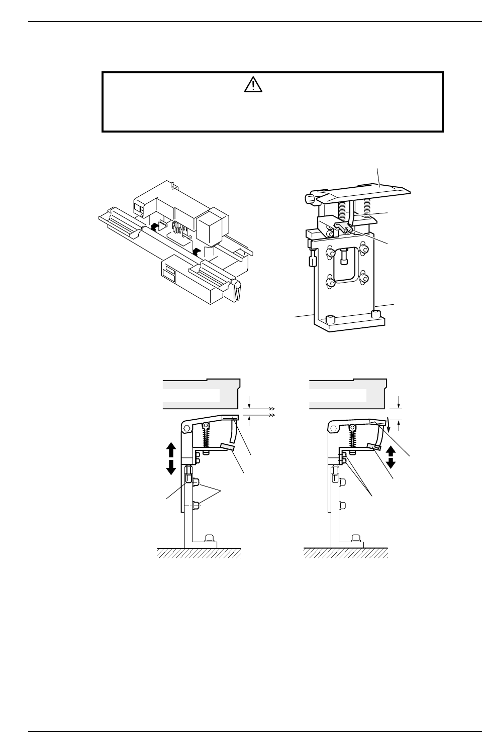
3.1.8 Bottom Feeder Lift Sensor Adjustment
WARNING
Always be sure to cut off the 200 V power before carrying out any
work.
1. Set the space between the feeder and the lever to be 0.2 mm.
2. Adjust the sensor height so the sensor goes on if a thickness of 0.7 mm feeder
gauge is inserted between the lower surface of the feeder and the lever
(suppressing the lever 0.5 mm).
Lever
Flag
Sensor
Feeder
Level
(by sight)
Fixed bolts
Lever
Sensor
Adjustment bolt
Lever height adjustment Sensor height adjustment
Adjustment bolts
0.2 mm 0.7 mm
Feeder
CP6M5038
Lever
Sensor
Part 5 Chapter 3 Station Adjustments
Edition 1.0 5-3-20 CP-6 Series Mechanical Reference
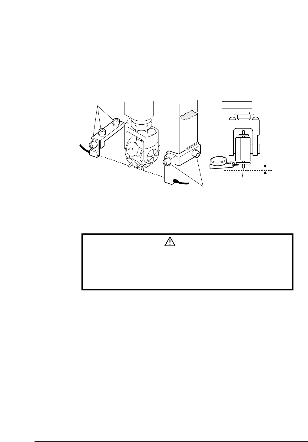
3.2 Station 2
3.2.1 Large Parts Check Sensor
The machine has a sensor at station 2 that checks for large parts (1 mm or larger). The
machine stops immediately if no part is detected.
Sensor Position Adjustment
1. Press the EMERGENCY STOP button. This cuts the 200V servo power and leaves
on only the 100V power supply.
WARNING
• Always be sure to cut off the 200 V power before carrying out any
work.
• Exercise extreme caution when working on the machine if the cam is
not at its origin (0 deg.). Recoil of the cam axis can endanger the
operator.
2. Use the cam handle to rotate the cam to 200°.
3. Set the dial gauge to the lower surface of the fluorescent sheet.
4. Adjust the sensor to go on with the tip of the nozzle lowered between 0.7 and 0.8
mm.
5. Actually pick up a part to check the sensor reaction.
Adjustment bolts
Adjustment bolts
Station 2
0.7
~ 0.8 mm
∅0.7 nozzle
Light
beam
CP6M5039
Part 5 Chapter 3 Station Adjustments
Edition 1.0 5-3-21 CP-6 Series Mechanical Reference