CP6的IO代码.pdf - 第236页
Part 5 Chapter 5 Servo Adjustments Edition 1.0 5-5-13 CP-6 Series Mechanical Reference Note: 1. After checking both X- and Y-axes using the UHi parameter, enter the mid parameter and verify that the travel time and maxim…

Part 5 Chapter 5 Servo Adjustments
Edition 1.0 5-5-12 CP-6 Series Mechanical Reference
Gain Adjustment
The adjustment procedure for the D-axis on the CP-642 and CP-643E machines is
identical.
<C- and X-Axis>
Connect the digital operator to the servo amplifier.
[DISP SET] → display [C][n][-][0][0] → [▲] → display [C][n][-][0][4]→ [DATA ENTER]
→ display [*][*][*][*] (Loop gain value) → [DATA ENTER] → [C][n][-][0][4]
<Y-, Z-, FQ-, FRQ- and NC-Axis>
Perform these adjustments from the panel operator
Press [MODE/SET] twice → display [P][n][0][0][0] → [▲] → panel display [P][n][1][0][0]
→ press [DATA/SHIFT] for 1 sec or longer → display [*][*][*][*] (Loop gain value)
→ press [DATA/SHIFT] for 1 sec or longer → display [P][n][1][0][0]
Loop Gain Values for Each Axis
Loop Gain Value
X → 80
Y → 60
Z → 60
Fθ → 100
FRθ → 100
NC → 250
C → 150
CP6M5083
Part 5 Chapter 5 Servo Adjustments
Edition 1.0 5-5-13 CP-6 Series Mechanical Reference
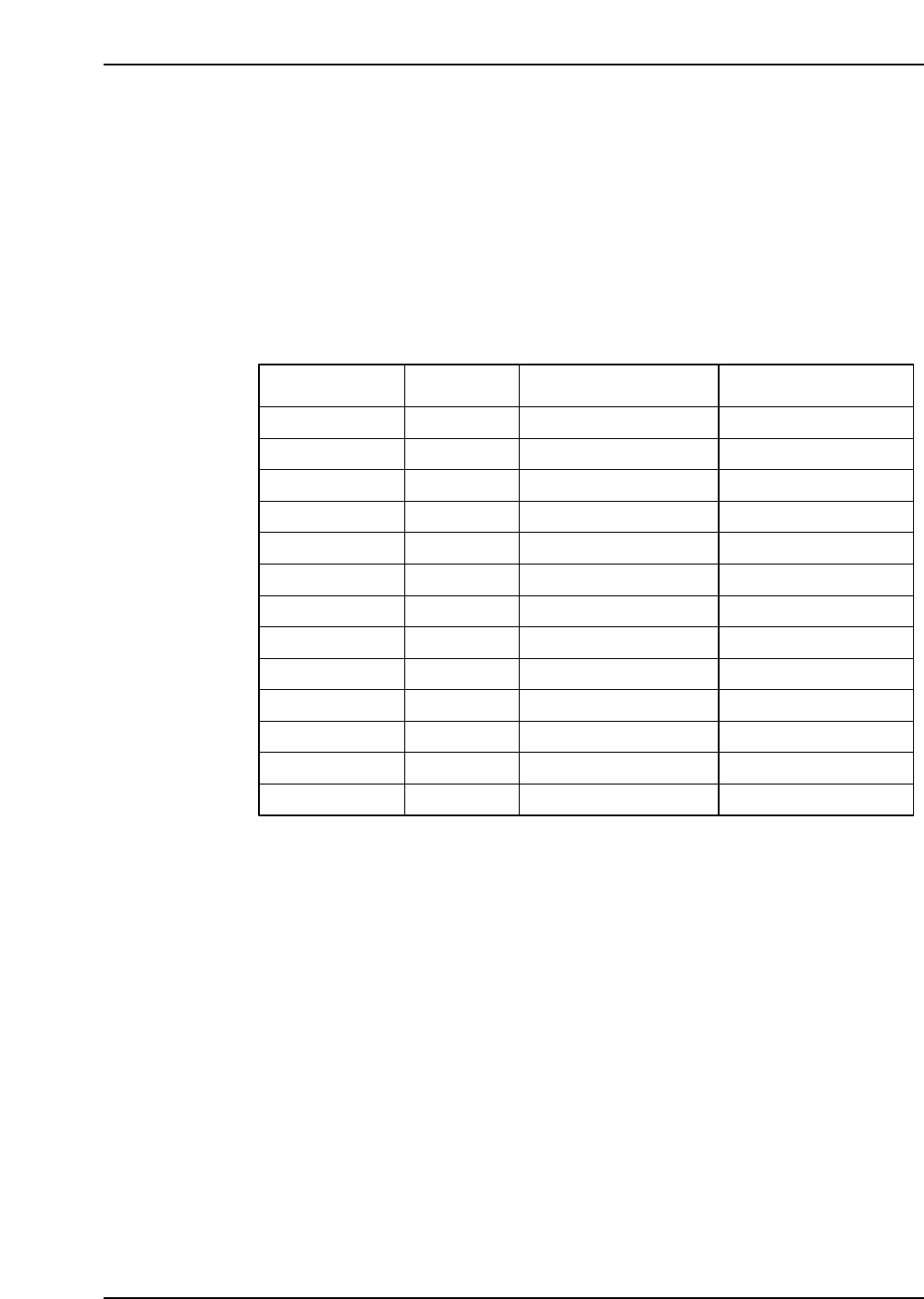
Note: 1. After checking both X- and Y-axes using the UHi parameter, enter the mid parameter and
verify that the travel time and maximum overshoot both fall within the ranges stated in
Table 1 “Max, Travel Time and Overshoot”.
2. After checking the FRQ-, FQ-, and NC-axes with the ROT parameter, enter the REV
parameter and verify that the travel time and maximum overshoot fall within the ranges
stated in table 1.
3. For digital input servo amplifiers, use a loop gain value specified above. No servo
adjustment is required.
If an axis does not satisfy the specs in table 1, check it again after idling the relevant axis.
Axis Condition Travel time (ms) Max, overshoot (pulse)
X UHi
X Mid
Y UHi
Y Mid
Z
C
D
FQ ROT
No load
56 ~ 59
FQ REV
FRQ ROT
FRQ REV
NC ROT
NC REV
200 degrees
200 degrees
200 degrees
0 degrees
0 degrees
0 degrees
0 ~ 4
0 ~ 4
0 ~ 4
0 ~ 4
0 ~ 5
0 ~ 4
2 ~ 4
0 ~ 4
0 ~ 4
0 ~ 4
0 ~ 4
0 ~ 5
0 ~ 4
56 ~ 59
56 ~ 59
56 ~ 59
52 ~ 54
166 ~ 171
72 ~ 73
29 ~ 35
26 ~ 32
29 ~ 35
26 ~ 32
19 ~ 22
30 ~ 34
Table 1 : Max,Travel Time and Overshoot
CP6M5084

Part 5 Chapter 5 Servo Adjustments
Edition 1.0 5-5-14 CP-6 Series Mechanical Reference
Notes: