CP6的IO代码.pdf - 第169页
Part 5 Chapter 2 Cam Box Edition 1.2 5-2-6 CP-6-series Mechanical Reference 2.3 Cam Origin Dog Adjustment (Cam Box) There is a cam axis origin dog in the cam box. With the cam angle at 0°, match the center of the dog wit…
Part 5 Chapter 2 Cam Box
Edition 1.2 5-2-5 CP-6-series Mechanical Reference
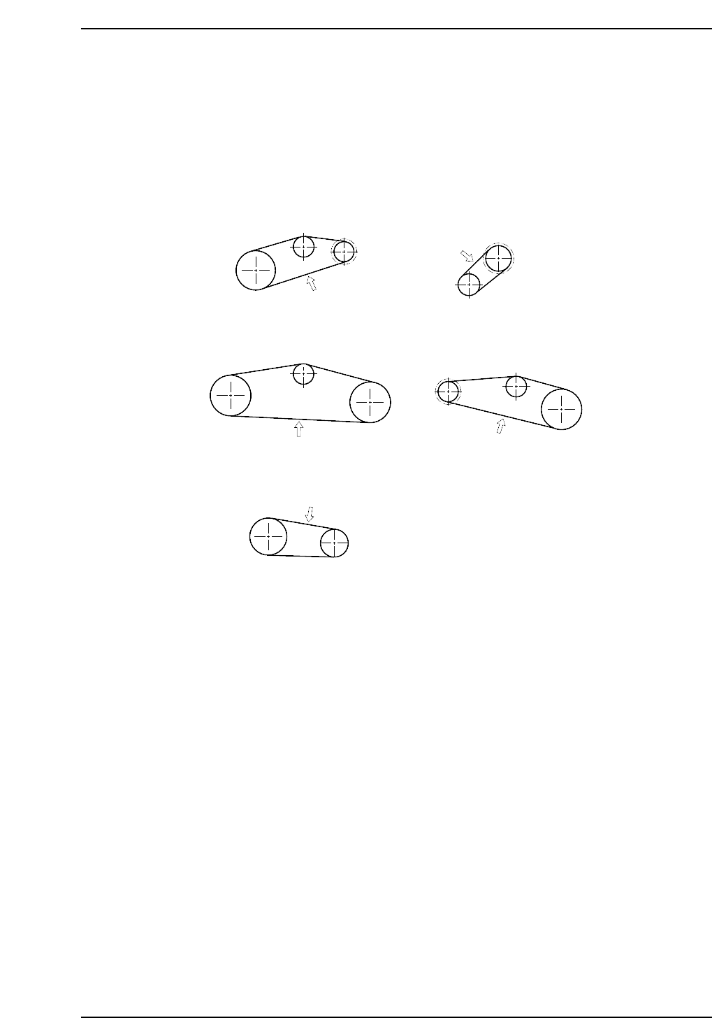
Adjustment procedure
First, adjust the tension of the belt between the idler pulley and the nozzle index unit
pulley (figure (b)). The belt tension can be changed using the adjustment bolts and by
moving the idler pulley. At this time make sure that there is no tension on belts (a), (d),
and (e).
Next, adjust belts (a), (c), (d) and (e) using the tension pulley. Refer to the figure below
for belt tension values.
• When measuring belt tension, ensure that the tension pulley is secured.
• Belts (c) and (d) are a set of two belts. Be sure to synchronize them so that the
numbers run sequentially.
• Even though belts (c) and (d) are a set, be sure to measure their individual
tensions.
(a)
(d)
(c)
(b)
(e)
90 ± 5 Hz
120 ± 5 Hz
69 ± 5 Hz
57 ± 5 Hz
121 ± 5 Hz
CP6M5009a
Part 5 Chapter 2 Cam Box
Edition 1.2 5-2-6 CP-6-series Mechanical Reference
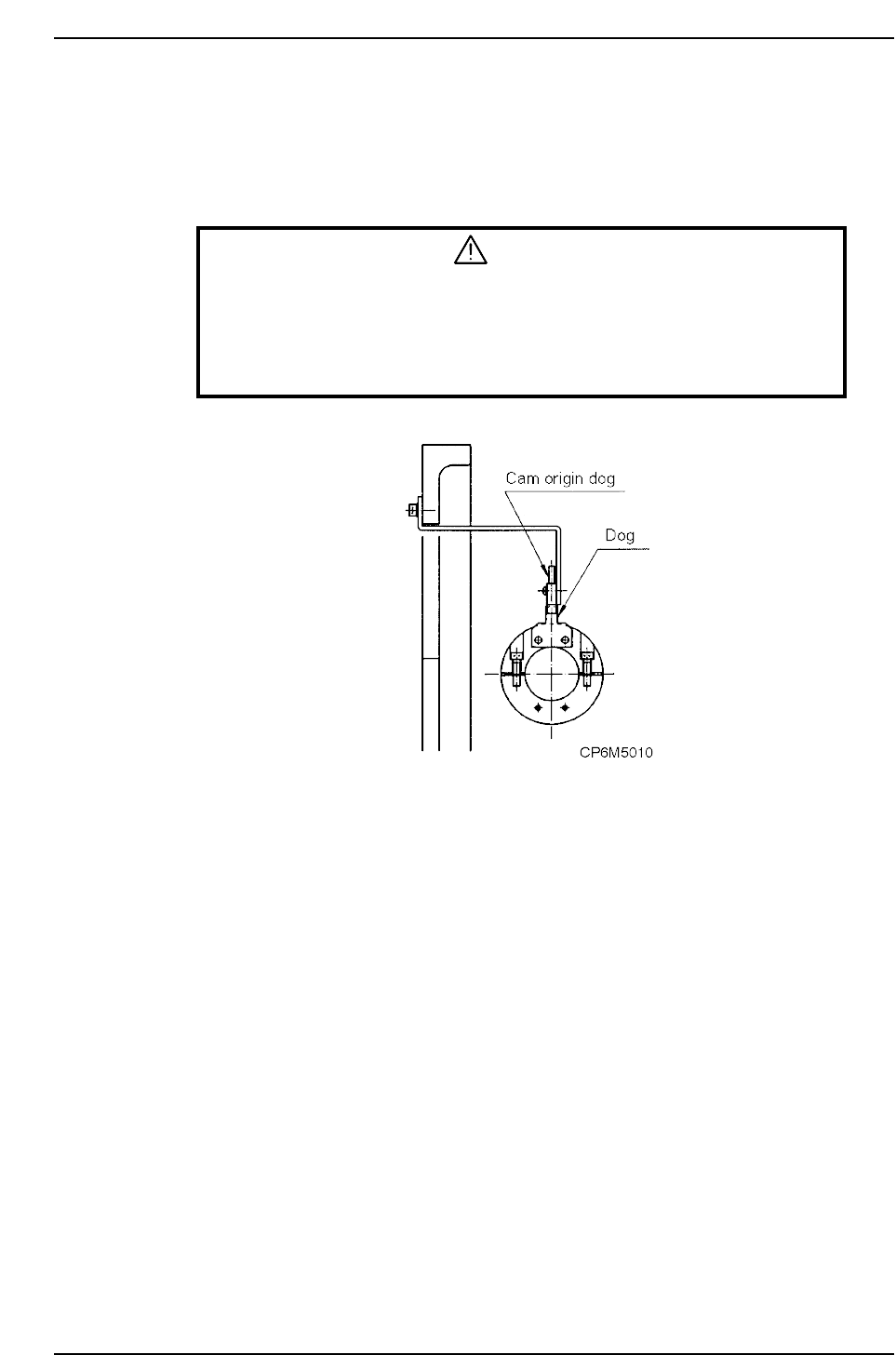
2.3 Cam Origin Dog Adjustment (Cam Box)
There is a cam axis origin dog in the cam box. With the cam angle at 0°, match the center
of the dog with the center of the sensor.
WARNING
• Always be sure to cut off the main power before carrying out any
work.
• Exercise extreme caution when working on the machine if the cam is
not at its origin (0 deg.). Recoil of the cam axis can endanger the
operator.
Part 5 Chapter 2 Cam Box
Edition 1.2 5-2-7 CP-6-series Mechanical Reference
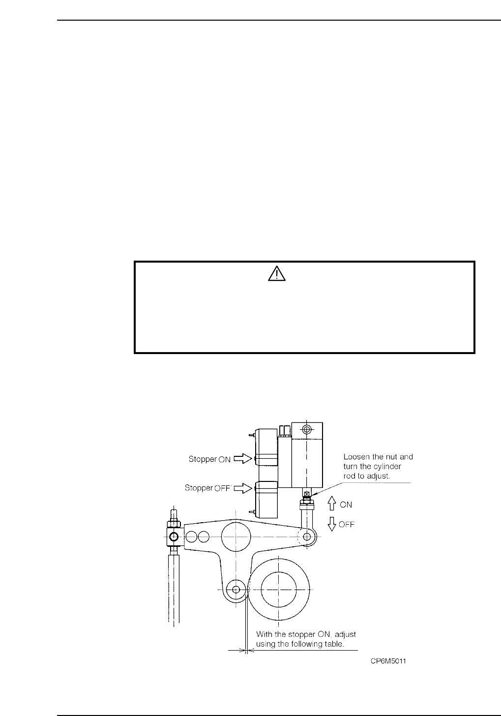
2.4 Cam Lever Stopper Adjustment (Cam Box)
The cam lever stopper operates through the movement of the air cylinder. Usually the
air cylinder is in the retract position. At this position the cam operates. When the air
cylinder is in the extended position, the lever action is stopped.
The stoppers are used on the following seven functions.
Station 1 UP & DOWN NOZZLE
Station 1 FWRD & BWRD, FEEDING JAW
Station 3 UP & DOWN CLUTCH
Station 10 UP & DOWN, F•θ
Station 11 UP & DOWN, NOZZLE
Station 13 UP & DOWN, PR•θ
Station 18 FWRD & BWRD, KNOTCH
Adjustment procedure
Perform the stopper adjustment using the following procedures.
WARNING
• Always be sure to cut off the 200 V power before carrying out any
work.
• Exercise extreme caution when working on the machine if the cam is
not at its origin (0 deg.). Recoil of the cam axis can endanger the
operator.
1. Set the cam to 0°.
2. Change the cylinder from the retract position to the extend position.
3. Attach a dial gauge to the end of the cam lever and set to zero.