OM-1271-003_w.pdf - 第49页
46 Tg1097-ID-OP 0708-002

45
Tg1097-ID-OP
0708-002
13. List of Consumables
13. List of Consumables
Listed below are the parts that may be consumed within one year.
Consult our marketing department or sales agency whenever you need to
purchase these parts.
Table 7
Product Name Part No. Part Name Q'ty
Recommended
Q'ty/Year
Note (a)
Exploded
View
Remarks
Vacuum Filter
630 069 5816 AIR LIN EQPT 3 18 Fig. MT-3
Note
(a) The numbers entitled "Recommended Q'ty/Year" indicate the
referential values.
(b) Refer to "11. Maintenance Spots" for the detailed information on how
to replace the parts with new ones.

46
Tg1097-ID-OP
0708-002
47
Tg1097-ID-OP
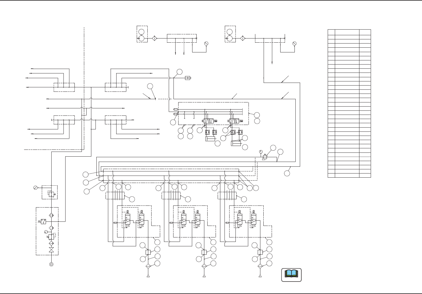
14. Pneumatic Diagram
14. Pneumatic Diagram
0708-002
2-PV
φ6
φ6
Setting
0.45MPa
Setting
φ8φ8
0.35MPa
φ8
φ6
φ6
φ8
φ8
φ8
φ6
φ6
φ6
φ6
φ6
φ6
φ6
φ8
φ10φ10
φ10
φ10
φ10
φ6
φ6
φ6
φ8
φ8
φ6
M
φ10
φ10
φ6
φ10
M
φ10
Setting
0.025MPa
φ4
Nozzle 2
AV
P
φ6
φ6
X
R
φ4
φ6
φ6
Nozzle 1
AV
P
φ6
φ6
X
R
φ4
φ6
φ6
Connection Cable φ6
Connection Cable φ8
Nozzle 3
φ8
φ6
φ6
AV
P
φ6
φ6
X
R
φ8
φ4
Stocker U/D
Shutter Opening and Closing
φ4
A
BB
AA
B
A
B
For Head 2,3
For Head 1,4
9
7
5
5
8
10
4
1
2
Bulk-head Union
5
5
6
9
7
5
5
8
10
9
7
5
5
8
10
12
5
11
14
13
2
18
For the Head No. 1 or 4,
it is attached on the nozzle side.
For Head No. 1 or 4,
connect from the Nozzle
No. 3 side.
15 16 17
12
5
11
12
5
11
φ6
Multi-functional Head (HM-G100)
(Example where the multi-functional
head is attached onto the Head No. 3 position).
Also, in the case of Head
No. 1, 2, or 4, fill up the bulk-head
union using the plug.
Also, in the case of Head No. 1, 2 or 4,
branch the air pipe at the same position and supply the air.
In the case of GXH-1J and 1JS, the air pipes for multi-functional
heads are arranged part of the way, so connect the pipe there.
For the multi-functional heads, connect to
the high-pressure (0.45 Mpa) air circuit.
Multi-Functional Nozzle Stocker
(Reference)
29
27
21
27
21
23
21
22
21
26
24
25
28
This diagram indicates as an example
of installing the Multi-Functional Head
to the Head #3
Note
<Piping for Stage 1>
Stage 1 (Rear) Nozzle Stocker
Stage 1 Transfer
To Head 1
To Head 2
To Head 4
To Head 3
Stage 1 (Rear) Feeder Base
Stage 1 (Rear) Feeder Clamp
Stage 2 (Rear) Nozzle Stocker
Stage 2 (Rear) Feeder Base
Stage 2 (Rear) Feeder Clamp
<Piping for Stage 2>
Stage 1 (Front) Nozzle Stocker
Stage 1 (Front) Feeder Base
Stage 1 (Front) Feeder Clamp
Stage 2 (Front) Nozzle Stocker
Stage 2 (Front) Feeder Base
Stage 2 (Front) Feeder Clamp
Stage 2 Transfer
Setting
0.05MPa
Vacuum Pump
(for Stage 1)
Vacuum Pump
(for Stage 2)
To Head 1 To Head 2
(Trans-
parent)
�
10
�
10
(Trans-
parent)
To Head 3
To Head 4
�
10
(Trans-
parent)
Bulkhead Union
Bulkhead Union
�
10
�
6
(Trans-
parent)
Straight Union
Throttle
Valve
Rerulater
1
2
3
4
5
6
7
8
9
10
26
Code
Code
Code
Plug
Union Y
Half Union
Half Union
Elbow Union
Solenoid
Valbe Unit
Plessure Sensor
Filter
27
Solenoid
Valbe Unit
17
18
19
20
21
22
23
24
25
Speed Controller
Plug
Straight Union
Plug
Plug
Half Union
Elbow Union
Elbow Union
11
12
13
14
15
16
Cylinder
Cylinder Unit
Solenoid
Valbe Unit28
29
30
NO Name
1
1
2
3
3
1
1
1
11
1
2
1
1
3
3
3
3
1
2
4
2
1
1
1
8
1
Q‘ty