OM-1271-003_w.pdf - 第57页
54 Tg1097-ID-OP X-Axis (A) Motor Circuit Diagram 0708 - 002 -(M 803 WC--A 2001 ) X-Axis (A) Motor Circuit Diagram X Beam Axis (A) X Axis From BG (A) From BG (A) Motion Controller 0 (-U82) From SSCNET2 CH1 T o BA-X221A Ro…
53
Tg1097-ID-OP
UA54 I/O Board ILB-IN 2 (R)
0708-002 A(M803WBR--A2004)
UA54 I/O Board ILB-IN 2 (R)
-U05
ILB
IN
1
2
3
3
2
1
3
2
1
3
2
1
1
2
3
1
2
3
1
2
3
3
2
1 1
2
3
3
2
1
3
2
1
3
2
1
1
2
3
1
2
3
1
2
3
3
2
1
CN28
CN27
CN26
CN25
CN24
CN23
CN22
CN21
-X0536
-X0535
-X0534
CN36
CN35
CN34
CN33
CN32
CN31
CN30
CN29
(UA54)
-X0521-X0521
M(D)
X30520D:2
X30520D:9
-517
Head Lowering (MD)
Reserved 1
Reserved 4
Reserved 3
Reserved 2
To -X8303:47
To -X8203:47
To -X8203:47
To -X8303:22
CPU2-R
CPU2-R
CPU2-R
To -X8203:22
To -X8203:22
Motion Control Board -U82
Motion Control Board -U83
Power Supply
Power Supply
Power Supply
Motion Control Board -U84
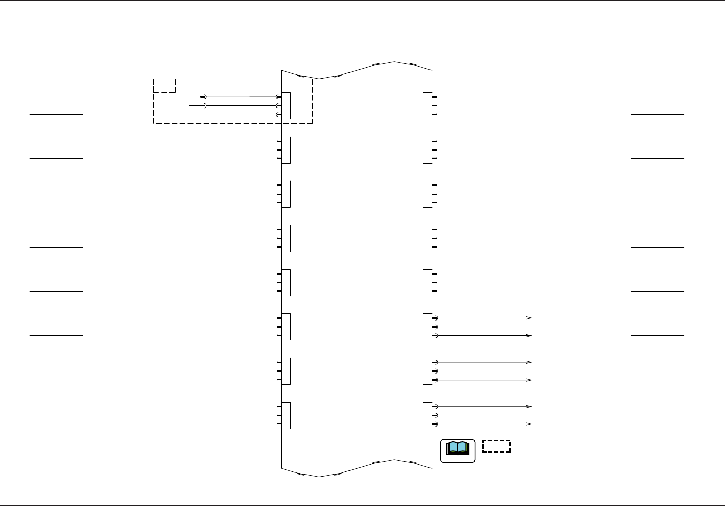
shows the circuit when the multi-functional head
is mounted.
When the multi-functional head is used in Stage C or D,
remove the corresponding connector to shortcut the current.
Note
54
Tg1097-ID-OP
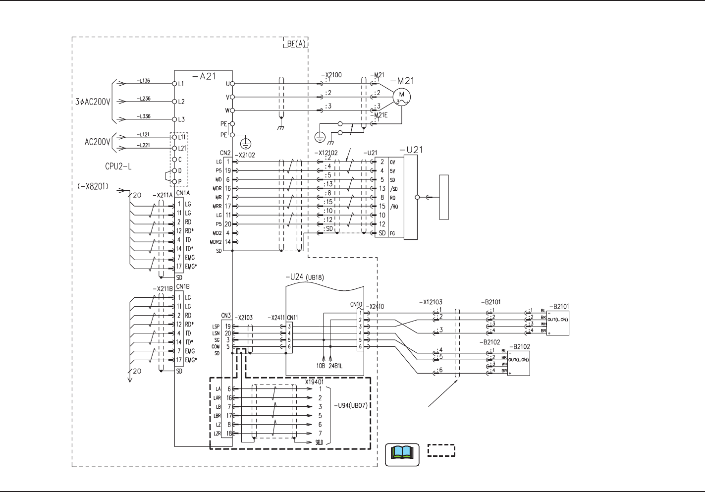
X-Axis (A) Motor Circuit Diagram
0708-002 -(M803WC--A2001)
X-Axis (A) Motor Circuit Diagram
X Beam Axis (A)
X Axis
From BG (A)
From BG
(A)
Motion Controller 0 (-U82)
From SSCNET2 CH1
To BA-X221A
Robot Cable
Robot Cable
Note
Recognition CPU
To Counter board
X-Axis Limit (+)
X-Axis Limit (-)
5V/Sensor
Linear Encoder
Converter
0V/Sensor
shows the circuit when the multi-functional
head is mounted.
Plate
55
Tg1097-ID-OP
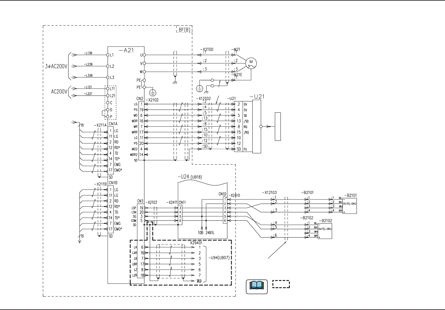
X-Axis (B) Motor Circuit Diagram
0708-002 B(M803WC--A2002)
X-Axis (B) Motor Circuit Diagram
Note
From BG (B)
From BG (B)
To BB-X221A
Robot Cable
Robot Cable
Recognition CPU
To Counter board
5V/Sensor
Linear Encoder
Converter
0V/Sensor
From BA-X231B
X Beam Axis (B)
X Axis
X-Axis Limit (+)
X-Axis Limit (-)
shows the circuit when the multi-functional
head is mounted.
Plate