OM-1271-003_w.pdf - 第62页
59 Tg1097-ID-OP 0708 - 002 B(M 803 WD--A 2017 ) UB13 I/O Board (Light T ower) UB13 I/O Board (Light T ower) shows the circuit when the multi-functional head is mounted. Note -U01 (UB13) Operation Panel Light T ower Relay…
58
Tg1097-ID-OP
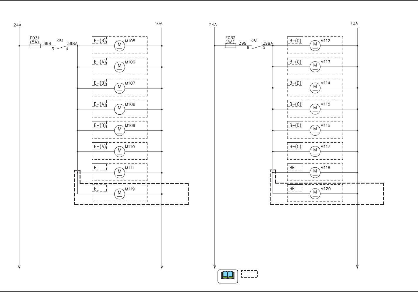
Main Body Cooling Fan Circuit Diagram
0708-002 -(M803WD--A2018)
Main Body Cooling Fan Circuit Diagram
Underframe Cooling Fan
(Front Left Side)
Underframe Cooling Fan
(Rear Left Side)
Overframe Cooling Fan
(Front Left Side)
Overframe Cooling Fan
(Rear Left Side)
Underframe Left Side
Cooling Fan (Front Side)
Underframe Left Side
Cooling Fan (Rear Side)
CPU2 (Left)
Cooling Fan
Underframe Cooling Fan
(Rear Right Side)
Underframe Cooling Fan
(Front Right Side)
Overframe Cooling Fan
(Front Right Side)
Overframe Cooling Fan
(Rear Right Side)
Underframe Right Side
Cooling Fan (Front Side)
Underframe Right Side
Cooling Fan (Rear Side)
CPU2 (Right) Cooling Fan
Electrical Box
(Left)
Cooling Fan
Electrical Box
(Right)
Cooling Fan
Note
shows the circuit when the multi-functional head is mounted.
59
Tg1097-ID-OP
0708-002 B(M803WD--A2017)
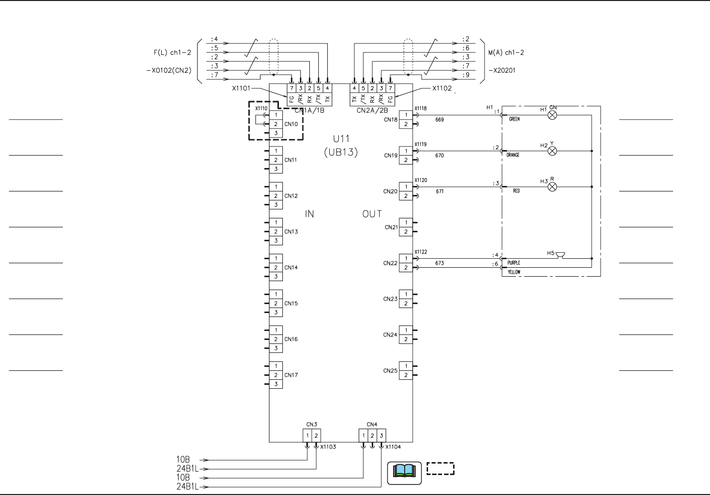
UB13 I/O Board (Light Tower)
UB13 I/O Board (Light Tower)
shows the circuit when the multi-functional head is mounted.
Note
-U01 (UB13) Operation Panel
Light Tower
Relay Connector Panel
Tower Light (Green)
Tower Light (Yellow)
Tower Light (Red)
Tower Light (Buzzer)
Multi-Functional Head
60
Tg1097-ID-OP
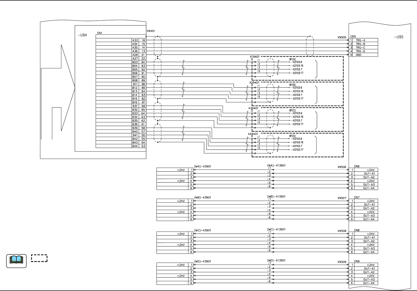
Recognition Connection Diagram (4)
0708-001 -(M803WR--A2001)
Recognition Connection Diagram (4)
shows the circuit when the
multi-functional head is mounted.
Note
Counter Board (UB07)
Bus
Recognition Box
CH0 Single Shot Output
CH1 Single Shot Output
CH2 Single Shot Output
CH3 Single Shot Output
GND
GND
CH0 Actuation A Phase Input +
CH0 Actuation A Phase Input -
CH0 Actuation B Phase Input +
CH0 Actuation B Phase Input -
CH0 Actuation Z Phase Input +
CH0 Actuation Z Phase Input +
CH1 Actuation A Phase Input +
CH1 Actuation A Phase Input -
CH1 Actuation B Phase Input +
CH1 Actuation B Phase Input -
CH1 Actuation Z Phase Input +
CH1 Actuation Z Phase Input +
CH2 Actuation A Phase Input +
CH2 Actuation A Phase Input -
CH2 Actuation B Phase Input +
CH2 Actuation B Phase Input -
CH2 Actuation Z Phase Input +
CH2 Actuation Z Phase Input +
CH3 Actuation A Phase Input +
CH3 Actuation A Phase Input -
CH3 Actuation B Phase Input +
CH3 Actuation B Phase Input -
CH3 Actuation Z Phase Input +
CH3 Actuation Z Phase Input +
(MA)-E39
PCB Recognition Lighting
(Beam A)
(MD)-E39
PCB Recognition Lighting
(Beam D)
(MB)-E39
PCB Recognition Lighting
(Beam B)
(MC)-E39
PCB Recognition Lighting
(Beam C)
PCB Recognition Lighting (Ring)
PCB Recognition Lighting (Coaxial)
PCB Recognition Lighting (OP)
(Reserved)
PCB Recognition Lighting (Ring)
PCB Recognition Lighting (Coaxial)
PCB Recognition Lighting (OP)
(Reserved)
PCB Recognition Lighting (Ring)
PCB Recognition Lighting (Coaxial)
PCB Recognition Lighting (OP)
(Reserved)
PCB Recognition Lighting (Ring)
PCB Recognition Lighting (Coaxial)
PCB Recognition Lighting (OP)
(Reserved)
Shell
Shell
Shell
Shell
A Phase
/A Phase
B Phase
/B Phase
To XA Axis -U24
A Phase
/A Phase
B Phase
/B Phase
To XB Axis -U24
A Phase
/A Phase
B Phase
/B Phase
To XC Axis -U24
A Phase
/A Phase
B Phase
/B Phase
To XD Axis -U24
Lighting Control Board (UB08)
Connector Case