OM-1271-003_w.pdf - 第67页
64 Tg1097-ID-OP Multi-Functional Head Motor Circuit Diagram 0708 - 001 -(M 803 WM--A 2012 ) Multi-Functional Head Motor Circuit Diagram It shows the circuit when the multi-functional head is mounted. DC5V Control Circuit…
63
Tg1097-ID-OP
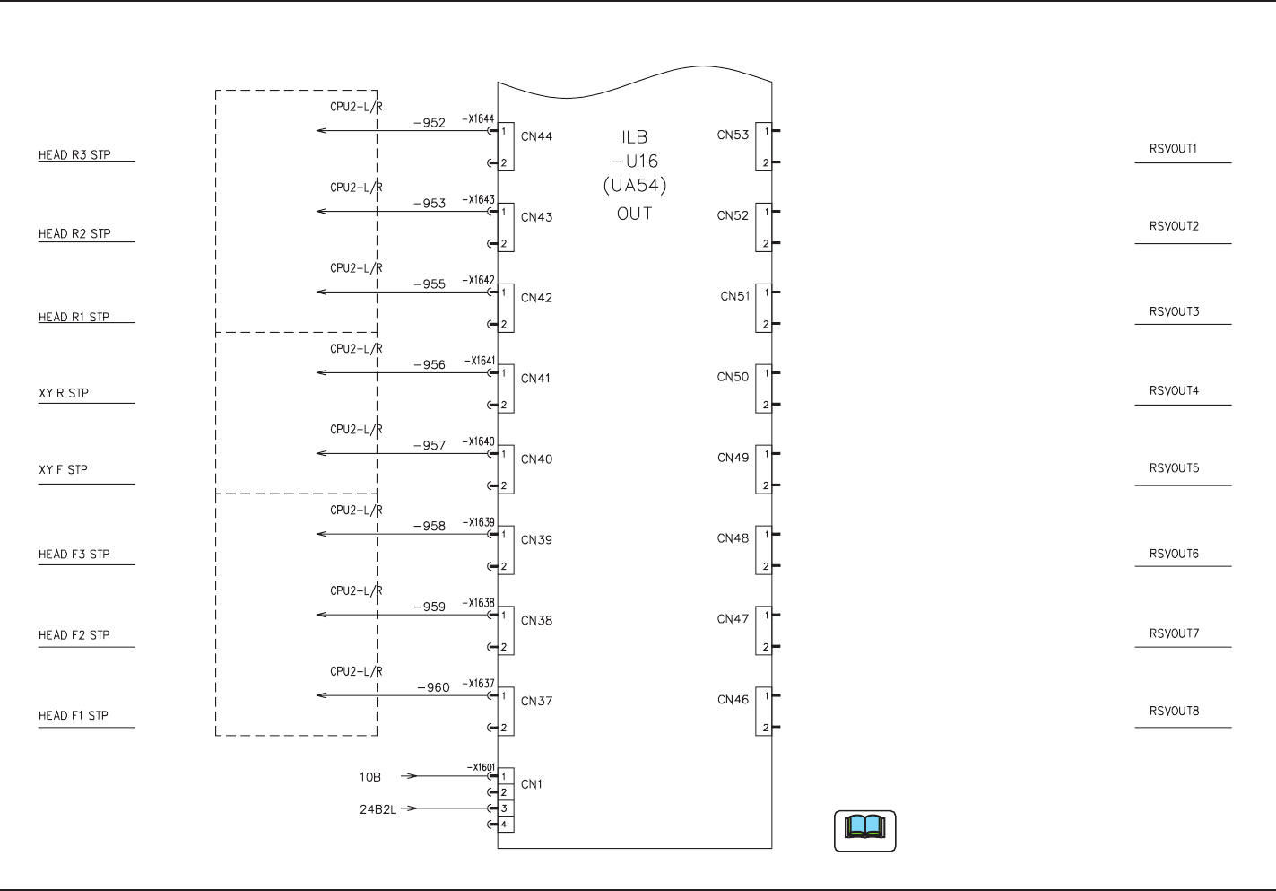
UA54 ILB-OUT (Multi-Functional Head)
0708-001 -(M803WM--A2011)
UA54 ILB-OUT (Multi-Functional Head)
It shows the circuit when the multi-functional
head is mounted.
Note
Motion Control PCB -U82
Motion Control PCB -U83
Motion Control PCB -U83
Motion Control PCB -U83
Motion Control PCB -U83
Motion Control PCB -U83
Motion Control PCB -U82
Motion Control PCB -U83
to -X8203:5
to -X8303:2
to -X8303:4
to -X8303:3
to -X8303:27
to -X8303:27
to -X8203:6
to -X8303:29
64
Tg1097-ID-OP
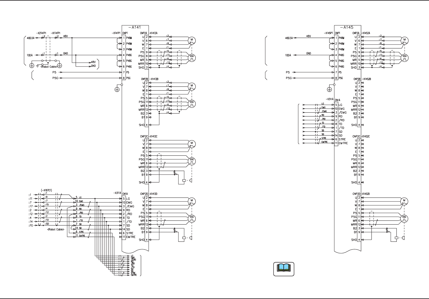
Multi-Functional Head Motor Circuit Diagram
0708-001 -(M803WM--A2012)
Multi-Functional Head Motor Circuit Diagram
It shows the circuit when the multi-functional head
is mounted.
DC5V
Control Circuit
Power Source
Main Circuit Power Source
DC48V
From -U28(UB28)
F(L)-X87C1
CPU2-L/R
From SSCNET Distribution PCB (-U87)
Nozzle 3 Z-Axis
Nozzle 2 Z-Axis
Blue
Blue
Yellow
White
Red
White
Green
Black
Red
-M141
-M141
Red
Black
Green
White
Orange
White
Yellow
Gray
Nozzle 2 L-Axis
-M142
Black
Red
Green
Red
Yellow
White
Blue
Blue
White
Black
Green
Orange
Yellow
White
Brown
Gray
White
Red
White
Gray
Brown
White
Yellow
Orange
Green
Red
Black
-M142
Nozzle 3 L-Axis
Gray
Yellow
White
Orange
White
Green
Black
Red
To -A145
CN1A
Note
From -U28(UB28)
Nozzle 1 Z-Axis
-M141
Gray
Yellow
White
Orange
White
Green
Black
Red Red
Black
Green
White
Red
White
Yellow
Blue
Blue
Lower SectionUpper Section
DC48V
Main Circuit Power Source
Control Circuit Power Source
DC5V
-M142
Black
Red
Green
Orange
Yellow
White
Brown
Gray
White
Nozzle 1 L-Axis
To CN1A
-A141
65
Tg1097-ID-OP
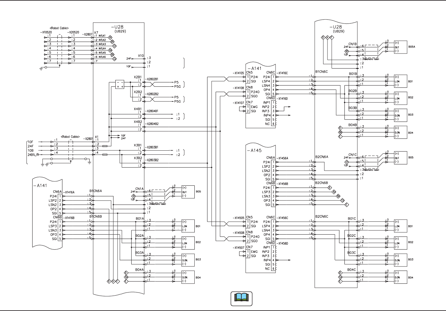
UB28 I/O Board (Multi-Functional Head)
0708-001 -(M803WM--A2013)
UB28 I/O Board (Multi-Functional Head)
It shows the circuit when the multi-functional head is mounted.
L Axis 3 +Limit
L Axis 3 -Limit
Excessive Press-in Detection 1
Black
Blue
Brown
To CN3(IN24V)
To CN4 (OUT24V)
-U27(UB13)
-U27(UB13)
Black
Blue
Brown
Brown
Blue
Black
Brown
Blue
White
Brown
Blue
White
To Multi-axis
Controller (CNP1)
To Multi-axis
Controller (CNP1)
Reserved
-A141,-A145
-A141,-A145
Brown
White
Gray
L Axis 3 pass line
L Axis 3 Origin
Vacuum Sensor 3
Automatic Shifting
-U17(UB13)
To -X1715(CN15)
Vacuum Sensor 2
Automatic Shifting
-U17(UB13)
To -X1716(CN16)
Vacuum Sensor 1
Automatic Shifting
-U17(UB13)
To -X1717(CN17)
Gray
Gray
Gray
L Axis 1 -Limit
L Axis 1 Origin
L Axis 1 pass line
L Axis 1 +Limit
White
Blue
Brown
White
Blue
Brown
Black
Blue
Brown
Brown
Blue
Black
L Axis 2 -Limit
L Axis 2 pass line
L Axis 2 +Limit
Excessive Press-in Detection 1
Excessive Press-in Detection 1
White
Blue
Brown
White
Blue
Brown
Black
Blue
Brown
Brown
Blue
Black
Brown
Blue
Black
Gray
White
Brown
Brown
White
Gray
Black
Blue
Brown
L Axis 2 Origin
Note