OM-1271-003_w.pdf - 第7页
Contents 4 Page Tg 1097 -ID-OP 0708 - 003 15. Electrical Circuit Diagram ............................................................... 48 UA54 ILB-IN 1 (Multi-Functional Head) .................................. 48 UA54…

Contents
3
Page
Tg1097-ID-OP
0708-003
Before Use ............................................................................................. 1
Contents .............................................................................................. 3
1. Scope ............................................................................................. 5
2. Specifications ................................................................................. 5
2.1 Standard Accessory Parts List ................................................ 8
3. Rough View .................................................................................... 9
4. Installation Position ........................................................................ 10
5. Nozzle Change in the "Set-up" Operation ...................................... 11
6. Nozzle Change in the Manual Operation ....................................... 14
7. Placement Head/Nozzle Data ........................................................ 16
8. Teaching ......................................................................................... 17
8.1 Head Rotation Angle Axis ....................................................... 17
8.2 Head Rotation Center Offset
/Basis Mark Position Teaching ............................. 19
8.3 Nozzle Stocker Offset ............................................................. 23
8.4 Head Nozzle Inclination Offset ............................................... 28
9. Periodic Maintenance ..................................................................... 31
9.1 Precautionary Items before Maintenance ............................... 31
9.2 Preparation for Maintenance .................................................. 32
9.2.1 Preparation for Cleaning ................................................ 32
9.2.2 Preparation for Lubrication ............................................ 33
10. Maintenance Check List ................................................................. 35
10.1 Weekly Maintenance .............................................................. 35
10.2 Monthly Maintenance .............................................................. 35
10.3 Quarterly Maintenance ........................................................... 36
11. Maintenance Spots ........................................................................ 37
11.1 Whole View ............................................................................. 37
11.2 Understanding of Maintenance Items on Each Section .......... 38
11.3 Inspection, Cleaning, and Lubrication Spots .......................... 39
11.3.1 Nozzle Stocker .............................................................. 39
11.3.2 Vacuum Nozzle .............................................................. 40
11.3.3 Placement Head ............................................................ 41
12. Replacement Procedure of Vacuum Filter ..................................... 43
13. List of Consumables ....................................................................... 45
14. Pneumatic Diagram ........................................................................ 47

Contents
4
Page
Tg1097-ID-OP
0708-003
15. Electrical Circuit Diagram ............................................................... 48
UA54 ILB-IN 1 (Multi-Functional Head) .................................. 48
UA54 ILB-OUT (Multi-Functional Head) ................................. 49
UA54 I/O Board ILB-IN 1 (L) ................................................... 50
UA54 I/O Board ILB-IN 2 (L) ................................................... 51
UA54 I/O Board ILB-IN 1 (R) .................................................. 52
UA54 I/O Board ILB-IN 2 (R) .................................................. 53
X-Axis (A) Motor Circuit Diagram ............................................ 54
X-Axis (B) Motor Circuit Diagram ............................................ 55
X-Axis (C) Motor Circuit Diagram ........................................... 56
X-Axis (D) Motor Circuit Diagram ........................................... 57
Main Body Cooling Fan Circuit Diagram ................................. 58
UB13 I/O Board (Light Tower) ................................................. 59
Recognition Connection Diagram (4) ...................................... 60
UA54 ILB-IN 1 (Multi-Functional Head) .................................. 61
UA54 ILB-IN 2 (Multi-Functional Head) .................................. 62
UA54 ILB-OUT (Multi-Functional Head) ................................. 63
Multi-Functional Head Motor Circuit Diagram ......................... 64
UB28 I/O Board (Multi-Functional Head) ................................ 65
UB13 I/O Board (Multi-Functional Head) ................................ 66
UB14 I/O Board (Positioning) A .............................................. 67
UB14 I/O Board (Positioning) B .............................................. 68
UB14 I/O Board (Positioning) C .............................................. 69
UB14 I/O Board (Positioning) D .............................................. 70
16. Cord Connection Diagrams ............................................................ 71
CPU2-L Cable Connection 1 ................................................... 71
CPU2-L Cable Connection 2 ................................................... 72
CPU2-R Cable Connection 1 .................................................. 73
CPU2-R Cable Connection 2 .................................................. 74
Counter Cable Change Connection ........................................ 75
Sensor Cable Creative Material .............................................. 76
Multi-Functional Head Wiring Block Diagram ......................... 77
UA54 (Multi-Functional Head) Wiring Block Diagram (BL) ..... 78
UA54 (Multi-Functional Head) Wiring Block Diagram (BR) .... 79
Multi-Functional Head UA54 Wiring Material .......................... 80
5
Tg1097-ID-OP
1. Scope
This unit manages the multi-functional components in the Direct Drive
Modular Mounter GXH series.
There are three nozzles, placed in series, for each head.
2. Specifications
Item Description Special Item
1. Model Name
HM-G100
2. Construction
•Multi-Functional Head : HM-G100
• Multi-Functional Nozzle Stocker : G-S003-06 (For the Blocks 1 and 4)
: G-S003-07 (For the Blocks 2 and 3)
• For attaching to the main body : G-S050-07
(GXH-1, 1S
For the Blocks 1 and 4)
: G-S050-08
(GXH-1, 1S For the Blocks 2 and 3)
3. Throughput Chip-Type Components : 24,000 CPH/4 Head
QFP : 20,000 CPH/4 Head
Note
: Excluding the PCB transition time under optimum conditions.
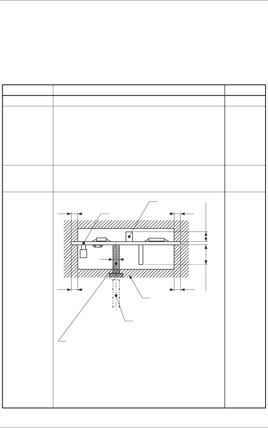
4. Conditions of
PCB before
Placement
(Regulation
of Component
Height)
Note :
The dimensions are those for design reference.
Leave some room for the actual setting.
3.0
PCB
PCB Support Pin
(Shows the time of PCB transfer.)
Previously-placed
Components Unallowed
Range
Component
3.0
3.0 3.0
4
Max. 25.4
PCB Support Pin (Several Places)
Notes: (a) The pin can be shifted at "20 mm" pitch.
(The shifting is partly possible at "10 mm" pitch.)
(b) Set the support pins such that they do not touch
the already placed components.
(c) The figure shows that the PCB is being supported.
(Front Side of Machine)
Max. 30
1. Scope
0708-003
Unit : mm