OM-1271-003_w.pdf - 第61页
58 Tg1097-ID-OP Main Body Cooling Fan Circuit Diagram 0708 - 002 -(M 803 WD--A 2018 ) Main Body Cooling Fan Circuit Diagram Underframe Cooling Fan (Front Left Side) Underframe Cooling Fan (Rear Left Side) Overframe Cooli…
57
Tg1097-ID-OP
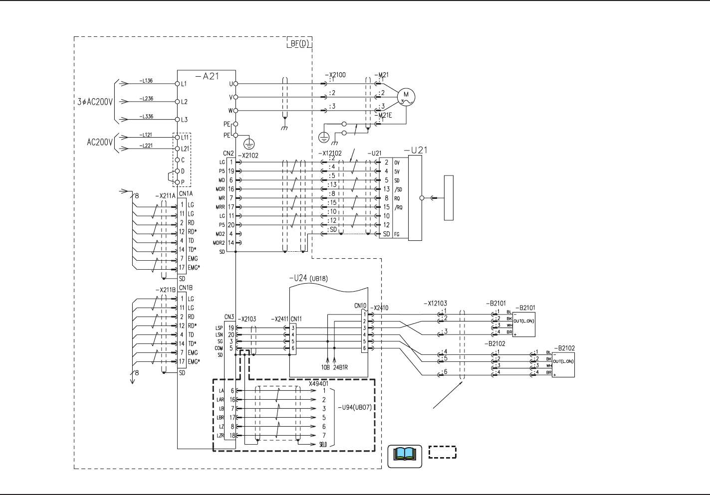
X-Axis (D) Motor Circuit Diagram
0708-002 B(M803WC--A2004)
X-Axis (D) Motor Circuit Diagram
Note
From BG (D)
From BG (D)
To BD-X221A
Robot Cable
Robot Cable
Recognition CPU
To Counter board
5V/Sensor
Linear Encoder
Converter
0V/Sensor
X Beam Axis (D)
X Axis
X-Axis Limit (+)
X-Axis Limit (-)
From BC-X231B
shows the circuit when the multi-functional
head is mounted.
Plate
58
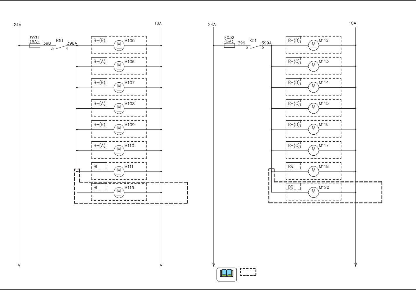
Tg1097-ID-OP
Main Body Cooling Fan Circuit Diagram
0708-002 -(M803WD--A2018)
Main Body Cooling Fan Circuit Diagram
Underframe Cooling Fan
(Front Left Side)
Underframe Cooling Fan
(Rear Left Side)
Overframe Cooling Fan
(Front Left Side)
Overframe Cooling Fan
(Rear Left Side)
Underframe Left Side
Cooling Fan (Front Side)
Underframe Left Side
Cooling Fan (Rear Side)
CPU2 (Left)
Cooling Fan
Underframe Cooling Fan
(Rear Right Side)
Underframe Cooling Fan
(Front Right Side)
Overframe Cooling Fan
(Front Right Side)
Overframe Cooling Fan
(Rear Right Side)
Underframe Right Side
Cooling Fan (Front Side)
Underframe Right Side
Cooling Fan (Rear Side)
CPU2 (Right) Cooling Fan
Electrical Box
(Left)
Cooling Fan
Electrical Box
(Right)
Cooling Fan
Note
shows the circuit when the multi-functional head is mounted.
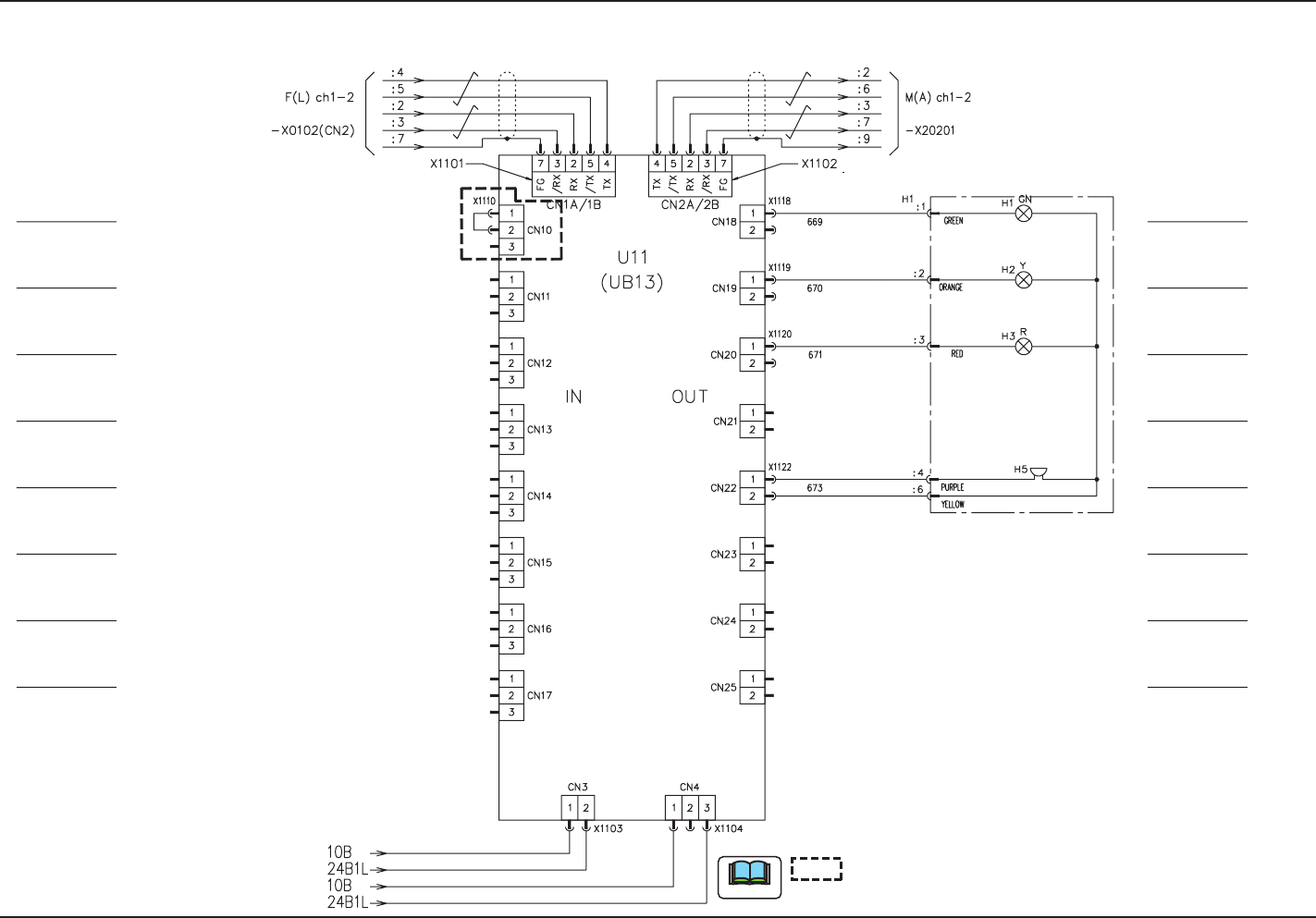
59
Tg1097-ID-OP
0708-002 B(M803WD--A2017)
UB13 I/O Board (Light Tower)
UB13 I/O Board (Light Tower)
shows the circuit when the multi-functional head is mounted.
Note
-U01 (UB13) Operation Panel
Light Tower
Relay Connector Panel
Tower Light (Green)
Tower Light (Yellow)
Tower Light (Red)
Tower Light (Buzzer)
Multi-Functional Head