OM-1271-003_w.pdf - 第83页
80 Tg1097-ID-OP Multi-Functional Head UA54 Wiring Material 0708 - 001 -(M 803 JSB--A 2077 ) Multi-Functional Head UA54 Wiring Material SW 5 SW 3 SW 4 SW 2 SW 1 CN5 CN13 CN21 CN29 CN30 CN22 CN14 CN6 CN7 CN15 CN23 CN31 CN3…
79
Tg1097-ID-OP
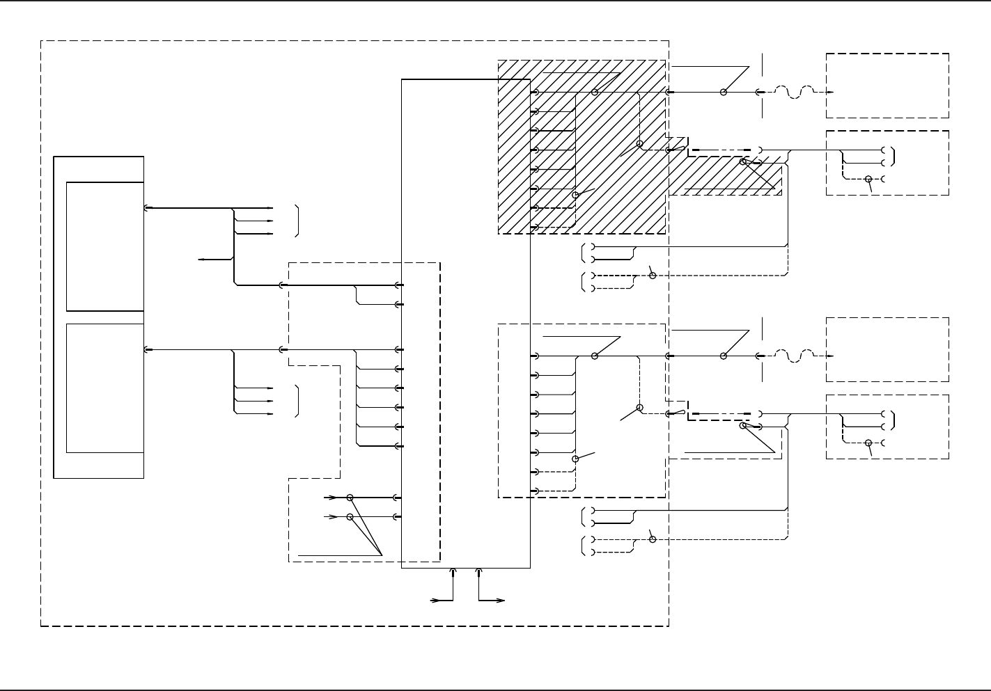
UA54 (Multi-Functional Head) Wiring Block Diagram (BR)
0708-001 -(M803JSB--A2072)
UA54 (Multi-Functional Head) Wiring Block Diagram (BR)
<Robot Cable>
-U28
(UB29)
To -X2807
(M803J*SB-A0047 Reference)
(M803J*SB-A0047
Reference)
To -X2807
(UB29)
-U28
<Robot Cable>
X10520B
CN10
CN9
CN8
CN7
CN6
CN5
-X1610
-X1609
-X1608
-X1606
-X1605
-X1607
CPU2-R
CN3 CN4
-X1603 -X1604
-U83
-X8303
Multi-Layer Tray
-X2506
-X0535
-X0550
-X0551
-X8203
-X0536
-X0554
-X0553
To UA54
-U05
-U82
-X1637
-X1638
-X1639
-X1640
-X1641
-X1642
-X1643
-X1644
CN37
CN38
CN39
CN40
CN41
CN42
CN43
CN44
-X1601
CN1
24B2L
24B1L
-U16
CN2
-X1602
CN18
CN17
CN16
CN15
CN14
CN13
-X1615
-X1614
-X1613
-X1618
-X1617
-X1616
(UA54)
X10520D
-U05
To UA54
1GG0W20009870
1GG0W20009880
1GG0W20009800A
1GG0W20009810A
(Standard Wiring)
1GG0W20009820
CN11
-X1611
CN12
-X1612
XB11611B
X30520B
For Nozzle Stocker op
For Nozzle Stocker op
CN19
-X1619
CN20
-X1620
For Nozzle Stocker op
XD11611D
For Nozzle Stocker op
X30520D
1GG4W20031170
1GG4W20031180
1GG0W20009910
-X0521
-X0515
-X1245
-X1244
ID:1
ID:0
(Lug)
(Lug)
-X0939
-X0938
XB1611
-U09
(UB14)
For Nozzle Stocker op
-U05
(UA54)
-U12
(UB14)
-X0520
-X0514
-X1243
-X1242
For Bad mark op
X30520B
XB1611B
D(C)
-X0939
-X0938
XB1611
-U09
(UB14)
For Nozzle Stocker op
-U05
(UA54)
-U12
(UB14)
X30520D
XD1611D
D(D)
C(C)
C(D)
(Standard Wiring)
1GG0W20009920
BR
for D HEAD
for C HEAD
For Bad mark op
(M803J*SB-A2052 Reference)
-X11641
-X11644
Connect it when the
nozzle stocker is to
be operated.
1GG0W20009930
Connect it when the
nozzle stocker is to
be operated.
1GG0W20009930
-U07(UA53)I/F
-U05(UA54)ILB
-X0502(CN4)
-X0710(CN10)
Motion Control
Motion Control
Multi-Functional
Head ILB
(Standard Wiring)
(Standard Wiring)
BL(A,B)/BR(C,D)Common
80
Tg1097-ID-OP
Multi-Functional Head UA54 Wiring Material
0708-001 -(M803JSB--A2077)
Multi-Functional Head UA54 Wiring Material
SW 5
SW 3
SW 4
SW 2
SW 1
CN5CN13CN21CN29
CN30 CN22 CN14 CN6
CN7CN15CN23CN31
CN33 CN25 CN17 CN9
CN8CN16CN24CN32CN36 CN28 CN20 CN12
CN35 CN27 CN19 CN11
CN10CN18CN26CN34
CN1CN2
81
TP4BTP4A
1 8
1 2
CN3CN4
4321
8 1 18 8 1 8 1
TP3D TP3C TP3B TP3A
54321
ON
6
ON
21
ON
21
ON
21
ON
21
3
1
2
-X1616
-U16
(UA54)
3
1
2
3
1
2
2
1
3
-X1617
-X1618
2
1
3
3
1
2
2
1
3
3
1
2
3
1
2
2
1
3
2
1
3
(UA54)
-U16
3
1
2
3
1
2
3
1
2
-X1608
-X1609
-X1610
CN53
CN41
CN49
CN50
CN42
CN44
CN52
CN51
CN43
CN39
CN47
CN48
CN40
CN38
CN46
CN37
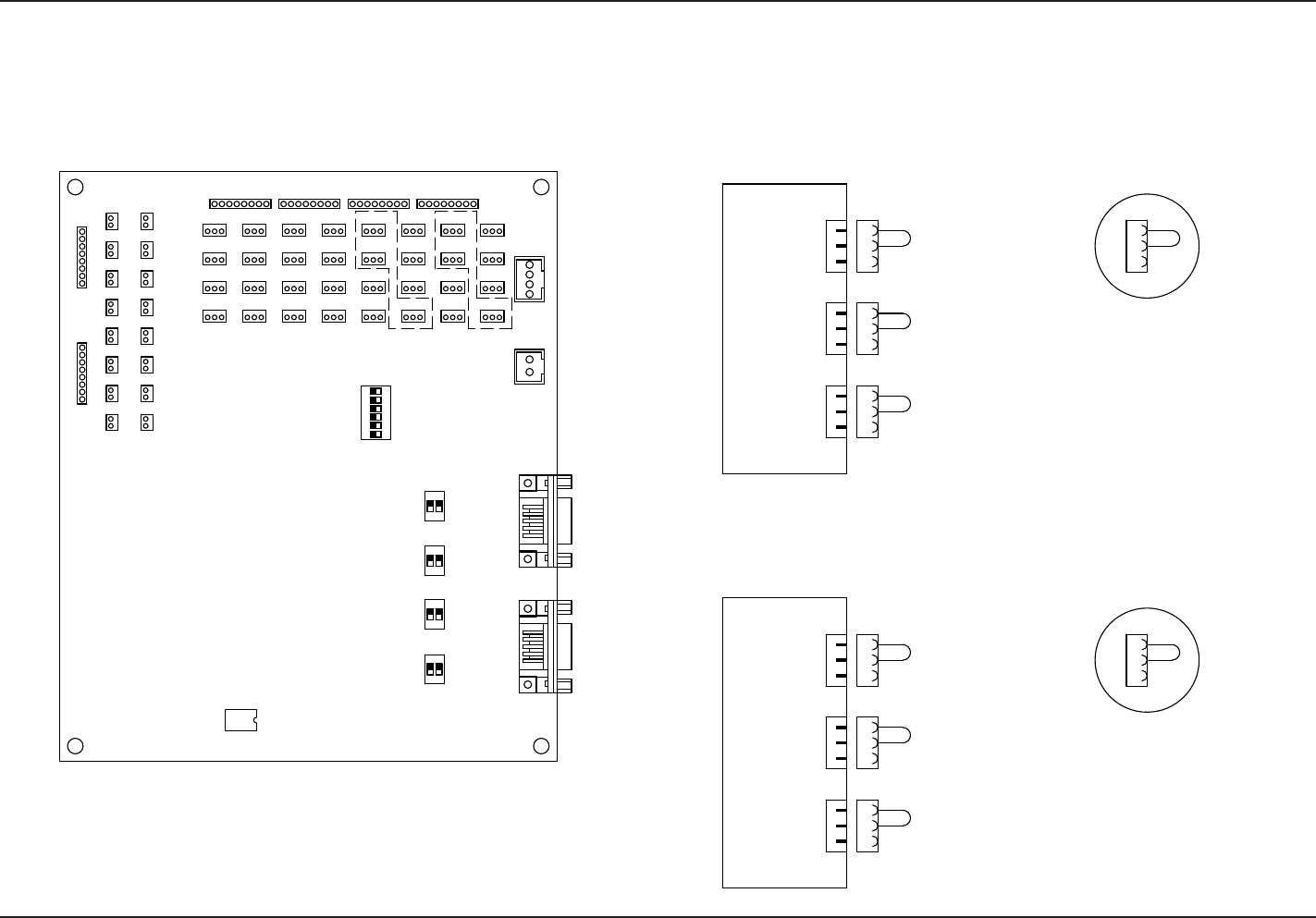
UA54 PCB Layout
View A
View A
When the cables for the multi-functional head are arranged to
the block A (rear left) or C (rear right), short cut the input terminals
on the unused side on the three locations as shown in the View A.
When the cables for the multi-functional head are arranged to
the block B (rear left) or D (rear right), short cut the input terminals
on the unused side on the three locations as shown in the View A.

81
Tg1097-ID-OP
0708-001