OM-1271-003_w.pdf - 第56页
53 Tg1097-ID-OP UA54 I/O Board ILB-IN 2 (R) 0708 - 002 A(M 803 WBR--A 2004 ) UA54 I/O Board ILB-IN 2 (R) -U05 ILB IN 1 2 3 3 2 1 3 2 1 3 2 1 1 2 3 1 2 3 1 2 3 3 2 1 1 2 3 3 2 1 3 2 1 3 2 1 1 2 3 1 2 3 1 2 3 3 2 1 CN28 CN…
52
Tg1097-ID-OP
UA54 I/O Board ILB-IN 1 (R)
0708-002 A(M803WBR--A2003)
UA54 I/O Board ILB-IN 1 (R)
Shielded
D-SUB 9PIN
Shielded
/RX
RX
/TX
TX
FG
-X0505
-X0506
-X0508
-X0509
-X0510
-X0511
-U05
CN5
CN6
CN7
CN8
CN9
CN10
CN11
CN12
-502
-501
-506
-507
-505
-504
9
3 72
67
9 63
2
FG
TX
/TX
RX
/RX
-X0504-X0503
CN4CN3
10B
24B1R
ILB
IN
1
2
3
3
2
1
3
2
1
3
2
1
1
2
3
1
2
3
1
2
3
3
2
1
24B1R
10B
10B
24B1R
10B
24B1R
10B
24B1R
1
2
CN2
-X0502
9 5
9 5
-K48
-K48
-512
802
803
-Q223 -Q222
-513
805
806
-Q223 -Q222
804
-Q221 -Q201
801
-Q221 -Q201
-515
-514
CN20
CN19
CN18
CN17
CN16
CN15
CN14
CN13
-X0520
-X0515
-X0514
-X0519
-X0518
-X0517
-X0516
1
2
3
3
2
1
3
2
1
3
2
1
1
2
3
1
2
3
1
2
3
3
2
1
DC
DD
10B
10B
10B
10B
(UA54)
:3
:4
:5
:2
:7
:7
:3
:6
:2
:9
10B
10B
RESERVED
RESERVED
RESERVED
RESERVED
-X1504
:1
:2
X504
:2
:1
X504
:2
:1
-X1504
M(C/D)
-510
-511
M(C)
M(D)
X30520C:1
X30520C:8
X30520D:1
X30520D:8
M(C)
X30520C:2
X30520C:9
-516
-X10511
-X10510
-B0510
-B0510
+
-
OUT1
:2
:3
:1
+
-
OUT1
:2
:3
:1
:1
:3
:2
:1
:3
:2
-X10508
-X10509
OUT2
OUT2
From K4 34
From K3 34
BR ch1-1
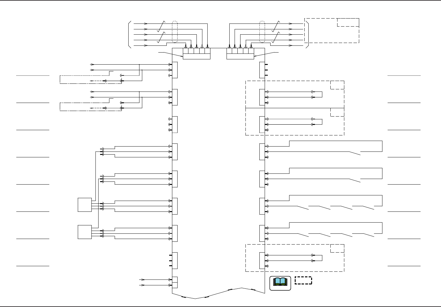
Multi-Layer Tray Feeder(R)
Emergency Stop
Safety Monitor
Safety Monitor for
Right Cover
-U12 (UB14)
Main Body
-X1202 (CN2)
Disengaged Suppressor
Detection (C)
Disengaged Suppressor
Detection (D)
Multi-Layer Tray Feeder(R)
CB Error(C-Y1)CB Error(C-Y2)
CB Error(D-Y1)CB Error(D-Y2) CB Error(Beam D Integral)CB Error(D-X)
CB Error(Beam C Integral)CB Error(C-X)
Nozzle Up/Down
Origin(MC)
Nozzle Up/Down
Origin(MD)
-U16(UA54)Multi-Functional Board
-X1603(CN3)
BR(R) ch1-1
Beam C CB Error Monitor
Beam D CB Error Monitor
Head Lowering (MC)
Beam C Main Power
Breaking Detection
Beam D Main Power
Breaking Detection
shows the circuit when the multi-functional head
is mounted.
When the multi-functional head is used in Stage C or D,
remove the corresponding connector to shortcut the current.
Note
Brown
Black
Blue
Orange
Brown
Black
Blue
Orange
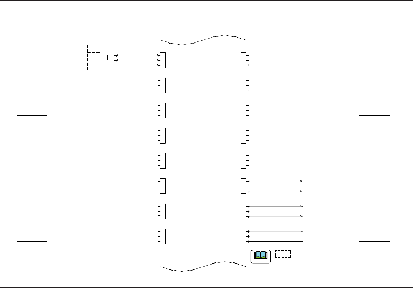
53
Tg1097-ID-OP
UA54 I/O Board ILB-IN 2 (R)
0708-002 A(M803WBR--A2004)
UA54 I/O Board ILB-IN 2 (R)
-U05
ILB
IN
1
2
3
3
2
1
3
2
1
3
2
1
1
2
3
1
2
3
1
2
3
3
2
1 1
2
3
3
2
1
3
2
1
3
2
1
1
2
3
1
2
3
1
2
3
3
2
1
CN28
CN27
CN26
CN25
CN24
CN23
CN22
CN21
-X0536
-X0535
-X0534
CN36
CN35
CN34
CN33
CN32
CN31
CN30
CN29
(UA54)
-X0521-X0521
M(D)
X30520D:2
X30520D:9
-517
Head Lowering (MD)
Reserved 1
Reserved 4
Reserved 3
Reserved 2
To -X8303:47
To -X8203:47
To -X8203:47
To -X8303:22
CPU2-R
CPU2-R
CPU2-R
To -X8203:22
To -X8203:22
Motion Control Board -U82
Motion Control Board -U83
Power Supply
Power Supply
Power Supply
Motion Control Board -U84
shows the circuit when the multi-functional head
is mounted.
When the multi-functional head is used in Stage C or D,
remove the corresponding connector to shortcut the current.
Note
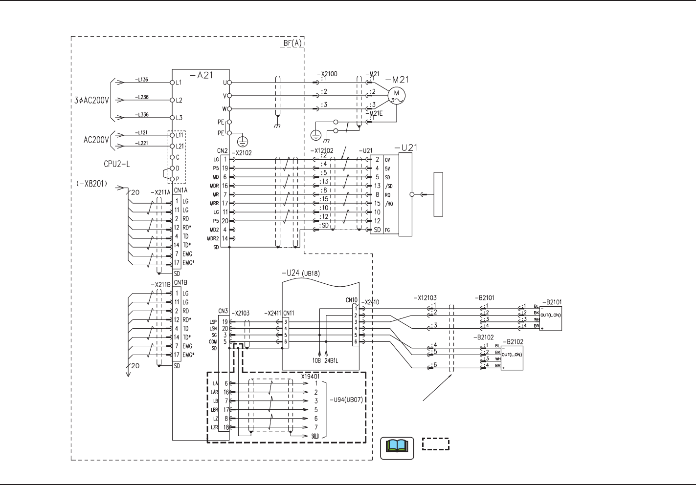
54
Tg1097-ID-OP
X-Axis (A) Motor Circuit Diagram
0708-002 -(M803WC--A2001)
X-Axis (A) Motor Circuit Diagram
X Beam Axis (A)
X Axis
From BG (A)
From BG
(A)
Motion Controller 0 (-U82)
From SSCNET2 CH1
To BA-X221A
Robot Cable
Robot Cable
Note
Recognition CPU
To Counter board
X-Axis Limit (+)
X-Axis Limit (-)
5V/Sensor
Linear Encoder
Converter
0V/Sensor
shows the circuit when the multi-functional
head is mounted.
Plate