P-TOOL说明书.pdf - 第69页
2-35 2 Board Explorer 4.2.4 How to set up 1 Select “Inspection program con version setting ” from the maintenance menu of the board explorer . Selecting [Inspector data con version setting] 642C2-S0-00 2 T urn on [Use In…
2-34
2
Board Explorer
l
Other parts
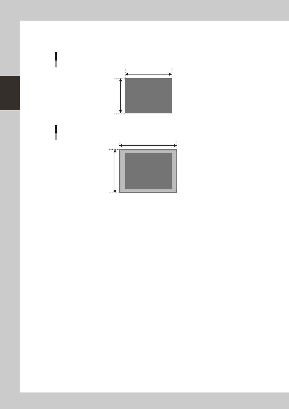
For the other parts as BGA, inspection step is set 1.1 times bigger than the parts size (maximum margin is 0..5mm for
each side) as below.
X (mm)
Y (mm)
Other parts ( except chip and lead parts)
63203-S0-00
Y *1.1
X *1.1
VADMIC inspection data of other parts
63204-S0-00
For each inspection step, by the data conversion, the default data is set as below.
•InspectionStatus :VADMIC
•ReferenceNumber :Patternnameofmounterboarddata
•PartsName :Partsnameofmounterboarddata
•Lib-partsName :Partsnamewhichissetinthepartsshapetable
•MountblockNo :Blocknumberofmounterboarddata
•Angle :Mountangleofmounterboarddata
•MinimumSizeX,Y:12(bodyinspection),6(solderorleadinspection)
•MinimumArea :25
•MatchingRatio :30
•DivideNumberX :PartsbodysizeX/300μm
•DivideNumberY :PartsbodysizeY/300μm
•LightingType :M(bodyinspection),
L-U(solderinspection),
BR2(leadinspection)
2-35
2
Board Explorer
4.2.4 How to set up
1
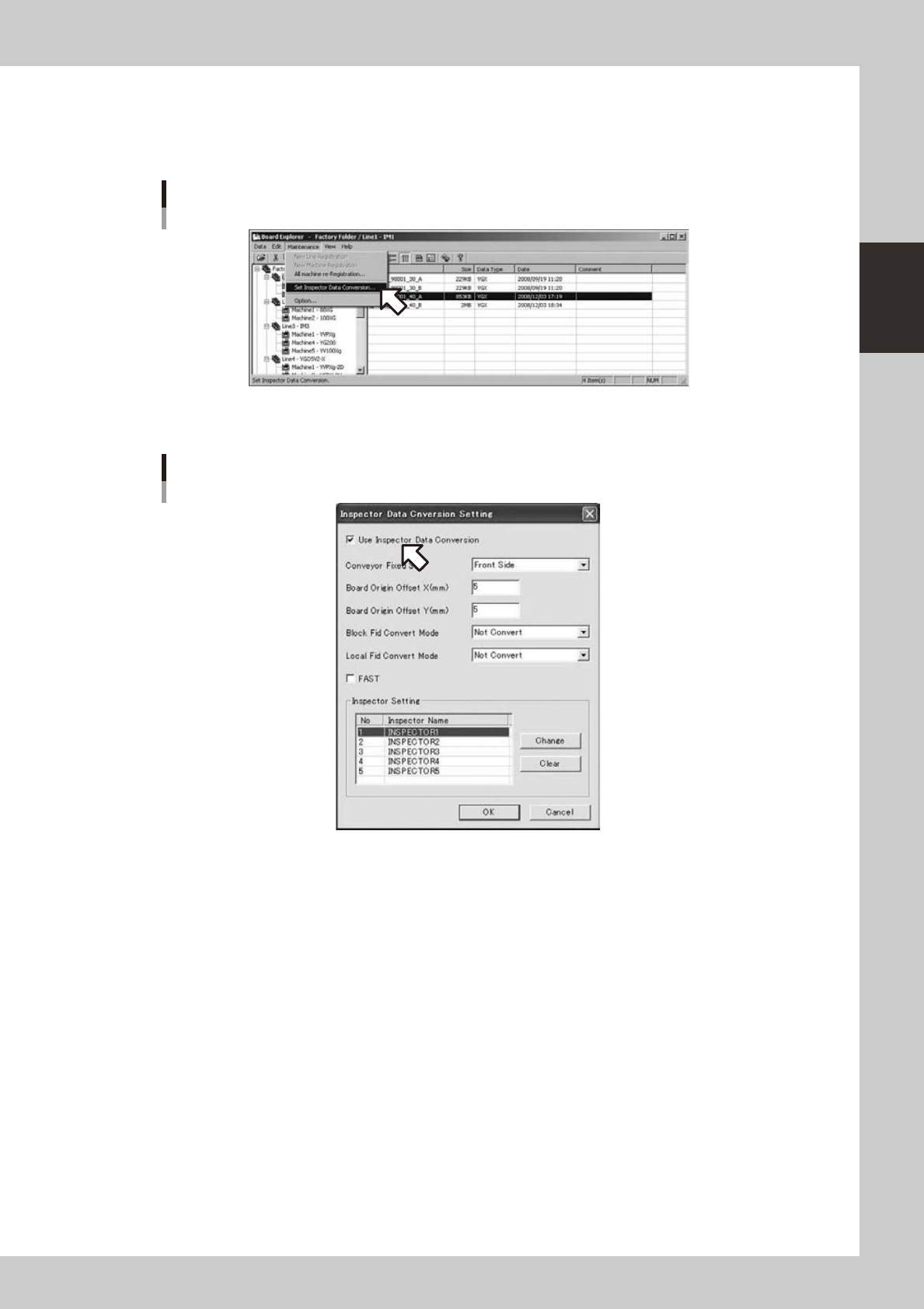
Select “Inspection program conversion setting” from the maintenance menu of the
board explorer.
Selecting [Inspector data conversion setting]
642C2-S0-00
2
Turn on [Use Inspection program conversion].
[Use inspector data conversion] is turned on
642C3-S0-10
2-36
2
Board Explorer
3
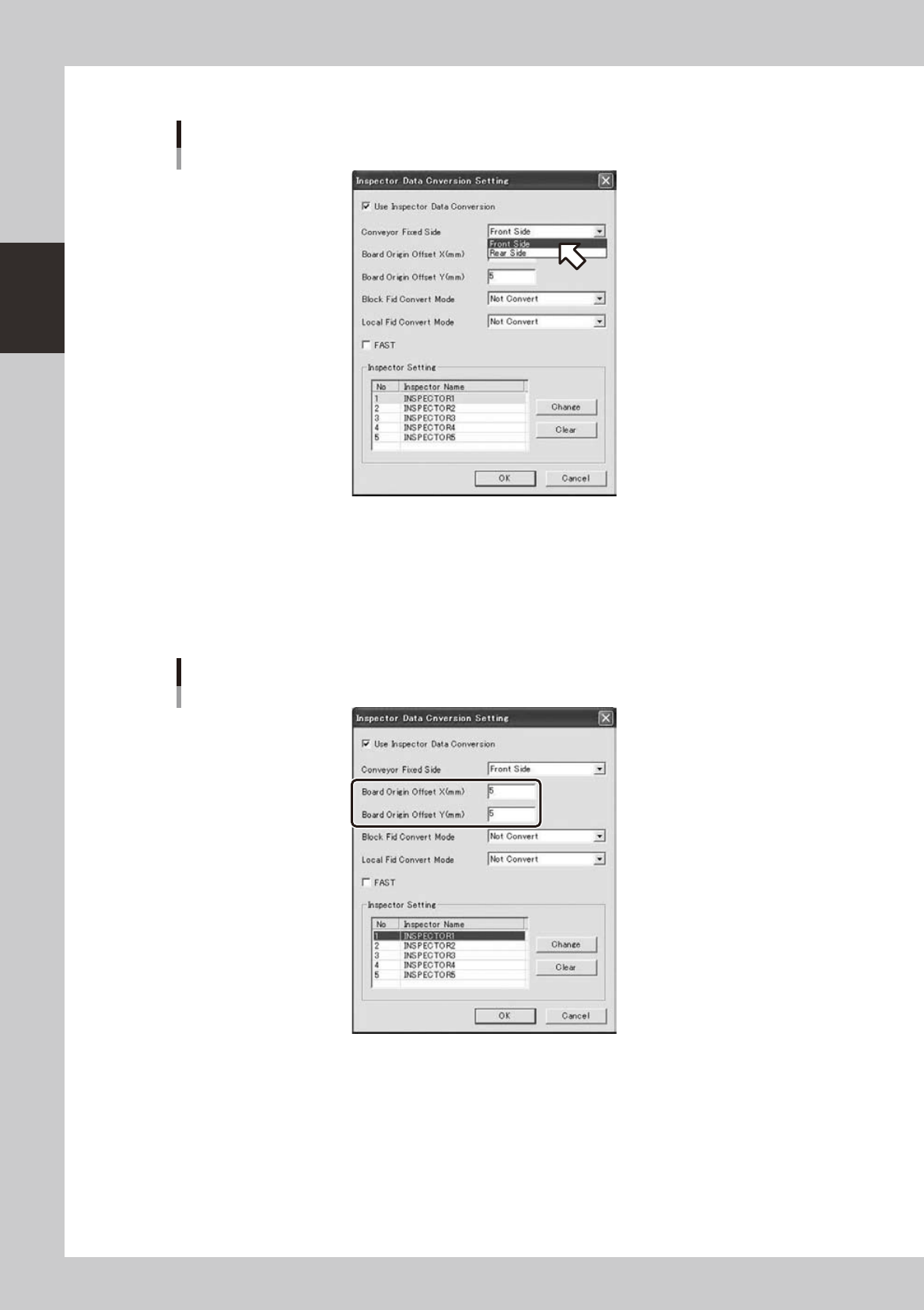
Set up conveyor on the fixed side.
Setting of conveyor on the fixed side
642C4-S0-10
Select front side when the conveyor of the mounter is fixed at front side: select rear side when fixed at
rear side.
4
Set up board origin references X and Y.
Set X=5.000 and Y=5.000 in normal use.
If the coordination of the converted Inspection program is misaligned, correct the value within a range
of -999.999 to 999.999.
Setting of board origin references X and Y
642C5-S0-10