YS12P_YS12F_YG12F_Mainte_E.pdf - 第47页
2-3 2 Daily maintenance items n How to check for clogged nozzles (on the [Unit]-[Head] tab screen) Theterm"cloggednozzle"usedhereindicatesthatmaterialsuchassolderisadheringtothenozzlehole, cau…
2-2
2
Daily maintenance items
1. Checking the nozzle
Solder sticking to the nozzle tip or a clogged nozzle hole can cause component pickup errors and
recognition errors. Poor nozzle spring action can also cause pickup and mounting errors. To prevent such
problems periodically inspect and clean each nozzle.
1.1 Check with software
n
How to check for a dirty nozzle (with the [Check Nozzle] button)
Theterm"dirtynozzle"asusedhereindicatesshinymaterialsuchassolderadheringtothenozzletip.This
shinyportionmightbemistakenforacomponentandcauserecognitionerrors.Tocheckforthisproblem,
pressthe[CheckNozzles]buttononthe[Setup]screenwhilethenozzletippicksupnocomponents.The
camerafindstheextentofgrimeordirtonthenozzletip.
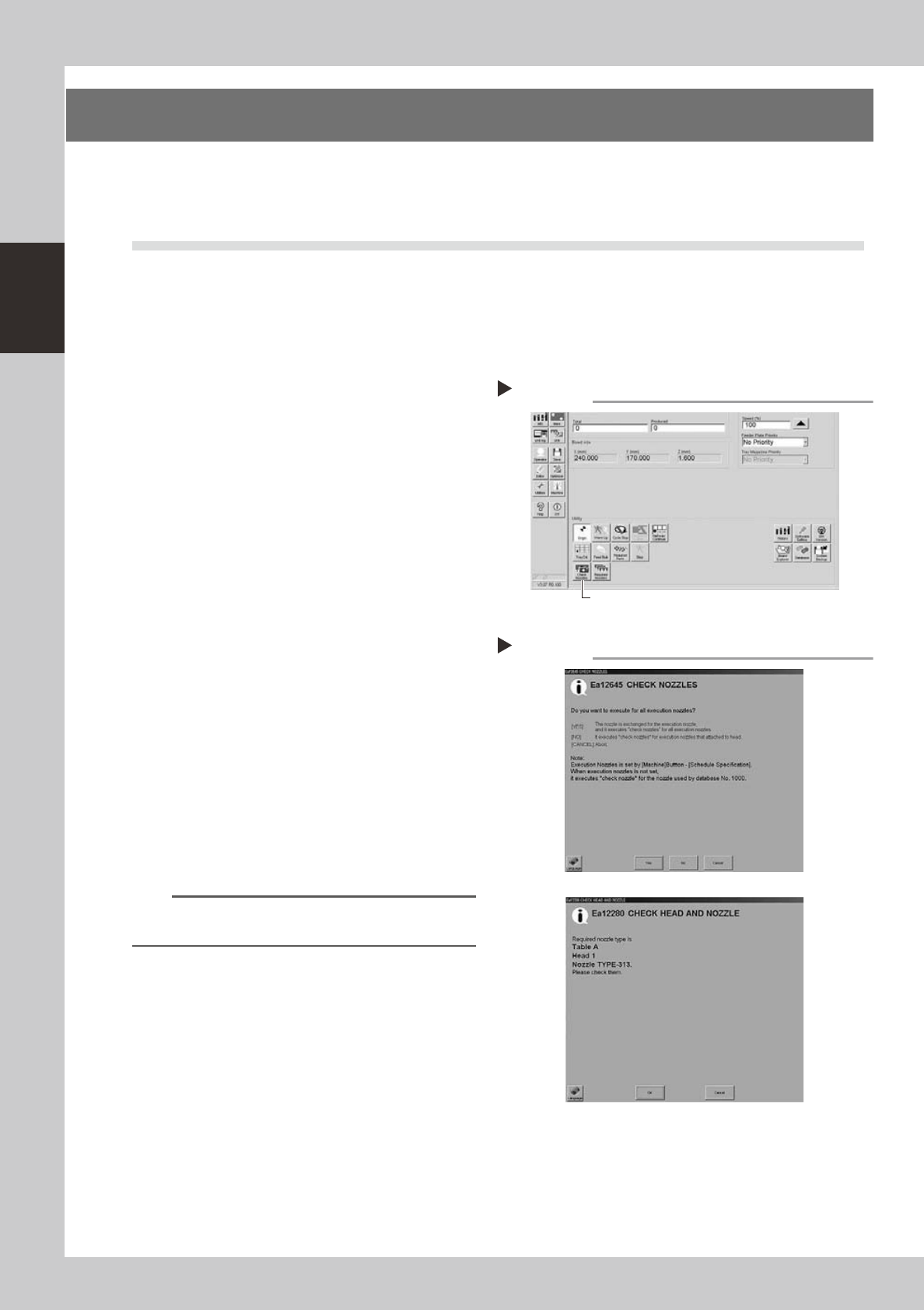
e
1
Move the head.
Press the emergency stop button and move
the head so the nozzle is at a position where
it can be easily replaced.
2
Press the [Check Nozzles] button as
follows.
1. Cancel emergency stop.
2. Open the [Setup] screen and press the
[Check Nozzles] button in "Utilities".
54201-L6-00
3
Select the item to be executed.
After checking the displayed message,
select the desired button.
n
When [Yes] was selected
Performsautonozzlechangeandchecksallnozzles
thatcanbechanged.
n
When [No] was selected
e
Checkthetargetnozzleinthenozzlescurrently
installedtotheheadassembly.
54202-L2-00
4
Check the message.
Clean the nozzle if the check shows it is dirty.
n
NOTE
The "Check Nozzles" function is usually set for "Type 302A
nozzles" before shipment.
Selecting the item to be executed
Step 3
When [No] was selected
Pressing the [Check Nozzles] button
Step 2
[Check Nozzles] button
2-3
2
Daily maintenance items
n
How to check for clogged nozzles (on the [Unit]-[Head] tab screen)
Theterm"cloggednozzle"usedhereindicatesthatmaterialsuchassolderisadheringtothenozzlehole,
causingariseinnegativepressureevenifnocomponentisbeingpickedupbythenozzle.Thisstatemight
causeproblemssuchascomponentmountingerrors.Checkforcloggednozzleswiththefollowingprocedure,
whichisdescribedusingType302Anozzlesasanexample.
e
1
Attach the nozzle.
Press the emergency stop button and attach
Type 302A nozzles to all heads. When the
machine has a nozzle station, press the
[Nozzle Change] button to change the
nozzles.
54204-L6-10
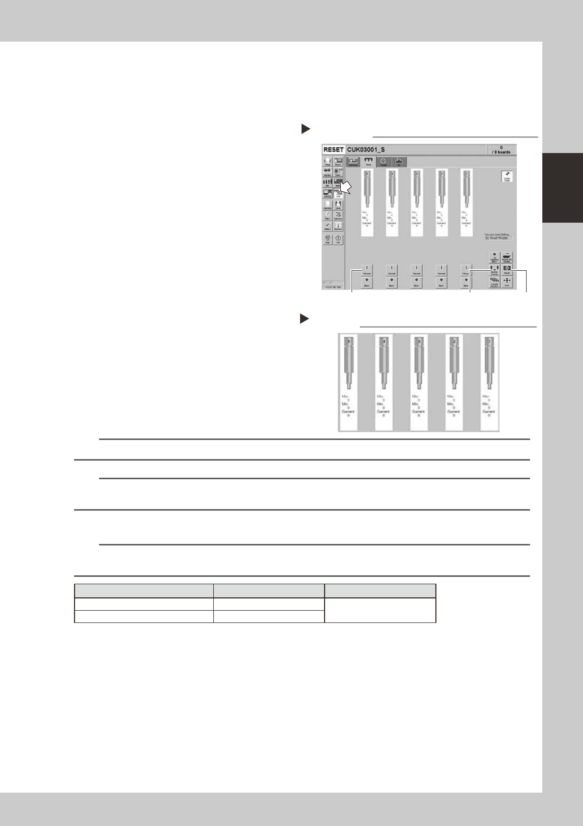
2
Reset the numerical figure.
Open the [Unit] - [Head] tab screen. Then
press the [Reset] button on the lower right of
the screen to reset the pickup level values.
3
Generate negative pressure.
On the [Unit] - [Head] tab screen, set the
[Vacuum] buttons for all heads to ON. When
this value starts rising, wait 5 to 10 seconds
and set to OFF.
4
Check the vacuum levels.
Read the "Max" value shown in red on the
[Head] tab screen. If this value is 110 or less
then it is in normal range. If higher than 110,
then the nozzle hole might be dirty and
probably needs cleaning.
54205-L6-00
n
NOTE
The above example is for Type 302A nozzles so the values shown will be different for other types of nozzles.
n
NOTE
If a correct value cannot be obtained after cleaning even after performing steps 1 to 4, then the interior of the spline
shaft might be dirty. To check it, refer to the table on the right.
n
Vacuum level in spline shaft air path (in spline shaft)
n
NOTE
The vacuum level in the spline shaft air path might sometimes differ slightly depending on the air source and operating
conditions. Use the above criteria values for reference during maintenance.
Nozzle Typical criteria when open Typical criteria when sealed
Type 303A (Type 314A) 85
190 or higher
No nozzle 70
Negative pressure generation
Step 1 to 3
[Nozzle Change] button[Vacuum] button [Reset] button
Negative pressure check
Step 4
2-4
2
Daily maintenance items
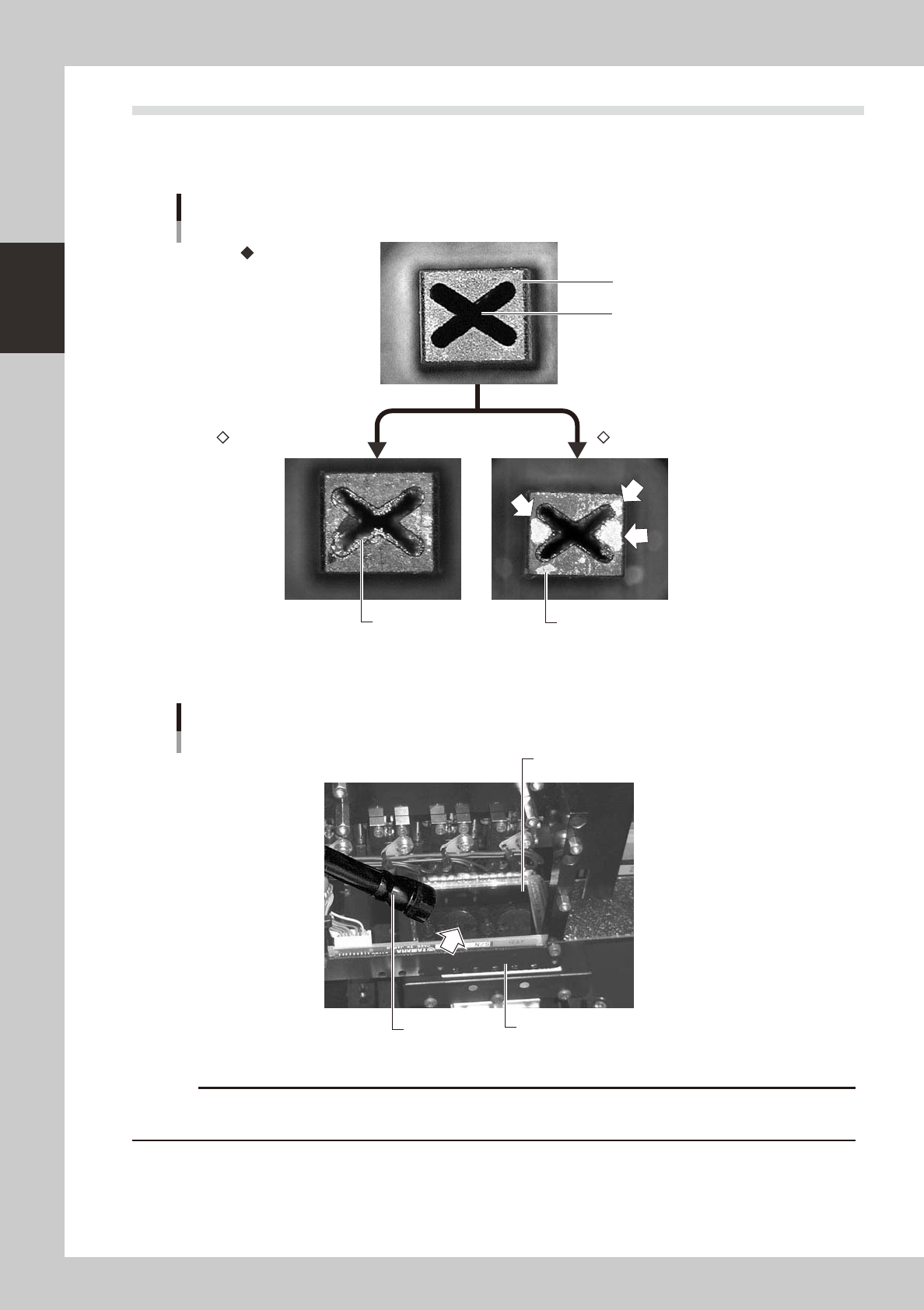
1.2 Checking the nozzles visually
Useeitherofthefollowingtwomethodstocheckthenozzletipvisually.
n
Remove the nozzle and check with a magnifying glass or similar tool.
Nozzle tip
Solder is adhering to nozzle hole
Solder is adhering to nozzle tip
Nozzle hole
Nozzle state
Normal condition
Clogged nozzle Shiny material on tip
53201-L6-00
n
Leave the nozzle installed and check with a hand mirror and flashlight.
Flashlight
Multi-vision camera
Hand mirror
Check with a hand mirror.
53202-L6-00
c