YS12P_YS12F_YG12F_Mainte_E.pdf - 第57页
3-5 3 Periodic maintenance items 1.3 Checking the board clamp condition and operation 1.3.1 Checking the board clamp condition Checkthefollowingpointstoseetheboardclampcondition. 1. Theboardisclampedwithout…
3-4
3
Periodic maintenance items
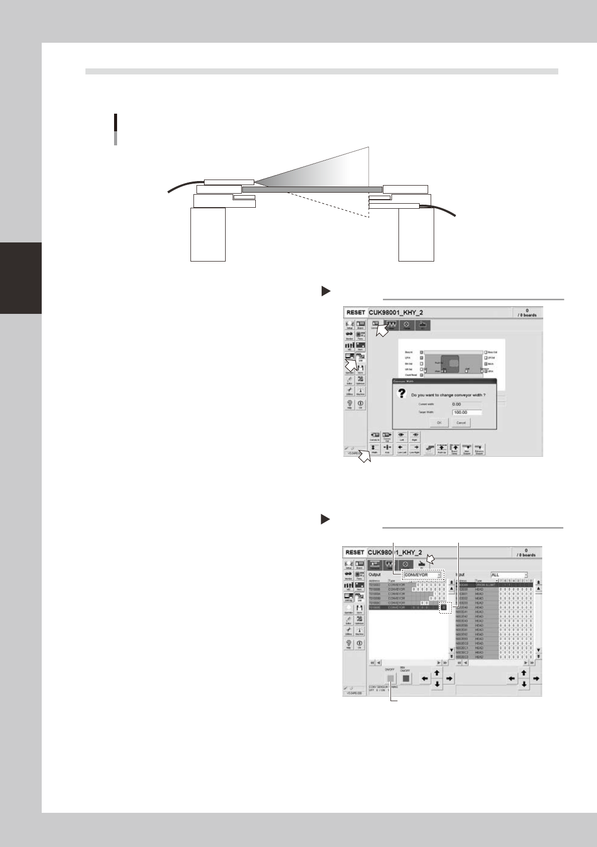
1.2 Checking the conveyor sensor condition and operation
Thismachineusesatransmissionmodefibersensorastheconveyorsensor.
Checkwhetherthesensoroperatescorrectlyevenwhentheconveyorrailwidthischanged.
Checking the conveyor sensor condition and operation
Light emitter
Light
sensor
53353-L6-00
1
Open the [Unit] – [Conveyor] tab.
2
Press the [Width] button to change
the conveyor width.
In the "Conveyor Width" dialog box that
appears, enter a conveyor width and press
[OK].
The conveyor is changed to the width that
was just entered.
3
Check whether an error has
occurred.
The conveyor sensor is operating properly
unless an error message appears when the
conveyor width is changed. No further check
is necessary.
54301-L6-00
n
If an error message appears, then adjust the sensor with the procedure below.
· Adjusting the conveyor sensor
Ifanerroroccurredwhentheconveyorwidthwas
changed,checktheoutputstatusoftheconveyor
sensor.
1.Openthe[Unit]–[I/O]tab.
2.Fromthe"Output"drop-downlist,select
"CONVEYOR".
3.Select"CONVSENSORTUNING"(T01000E)inthe
outputI/Olist.
4.Pressthe[ON/OFF]buttontoswitchtheI/Ostatus
from"0"(OFF)
→
"1"(ON)
→
"0"(OFF)toperform
autotuning.
5.Onthe[Unit]–[Conveyor]tab,pressthe[Axis]
buttonagainandchangetheconveyorwidth.The
sensorisoperatingproperlyunlessanerrormessage
appears.
54302-L6-00
Checking the conveyor sensor
Step 1-3
Conveyor sensor tuning
2
3
4
3-5
3
Periodic maintenance items
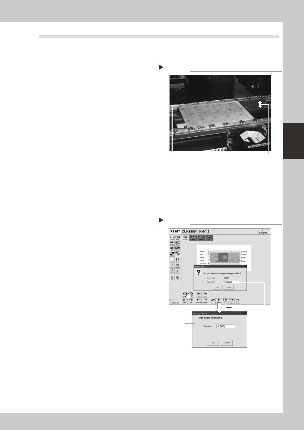
1.3 Checking the board clamp condition and operation
1.3.1 Checking the board clamp condition
Checkthefollowingpointstoseetheboardclampcondition.
1.Theboardisclampedwithoutplaywhentheboard
clampisraised.
2.Thereisnoclearancebetweentheboardandthe
boardholdplatewhentheboardclampisraised.
3.Theboardisflushwiththeuppersurfaceofthe
conveyorrailswhentheboardclampisraised.
4.Theboardclampunitmovessmoothly.
53301-L6-00
1.3.2 Checking the board clamp operation
1
Open the [Unit] – [Conveyor] tab.
2
Press the [Width] button to set the
conveyor width.
In the "Target Width" box in the "Conveyor
Width" dialog box that appears, enter the
board width and press [OK].
The conveyor is changed to the width that
was just entered.
3
Press the [Push Up] button to enter
the board thickness.
In the dialog box that appears, enter the
board thickness and press [OK].
4
Press the [Board Clamp] button to
clamp the board.
5
Press the [Board Clamp] button
again to unclamp the board.
54309-L6-00
Repeatsteps4and5toclampandunclampthe
boardtomakesuretheclampunitoperates
smoothly.
Checking the clamp condition
Check that there is no clearance
between the board and board hold
plate and also that the board is flush
with the conveyor rails.
Clamp and unclamp the
board to check the
movement.
Checking the clamp operation
Step 2-5
Step2
Step3
Step4, Step5
3-6
3
Periodic maintenance items
2. Monthly or bimonthly inspection
This section mainly explains the cleaning and lubrication procedures after inspection.
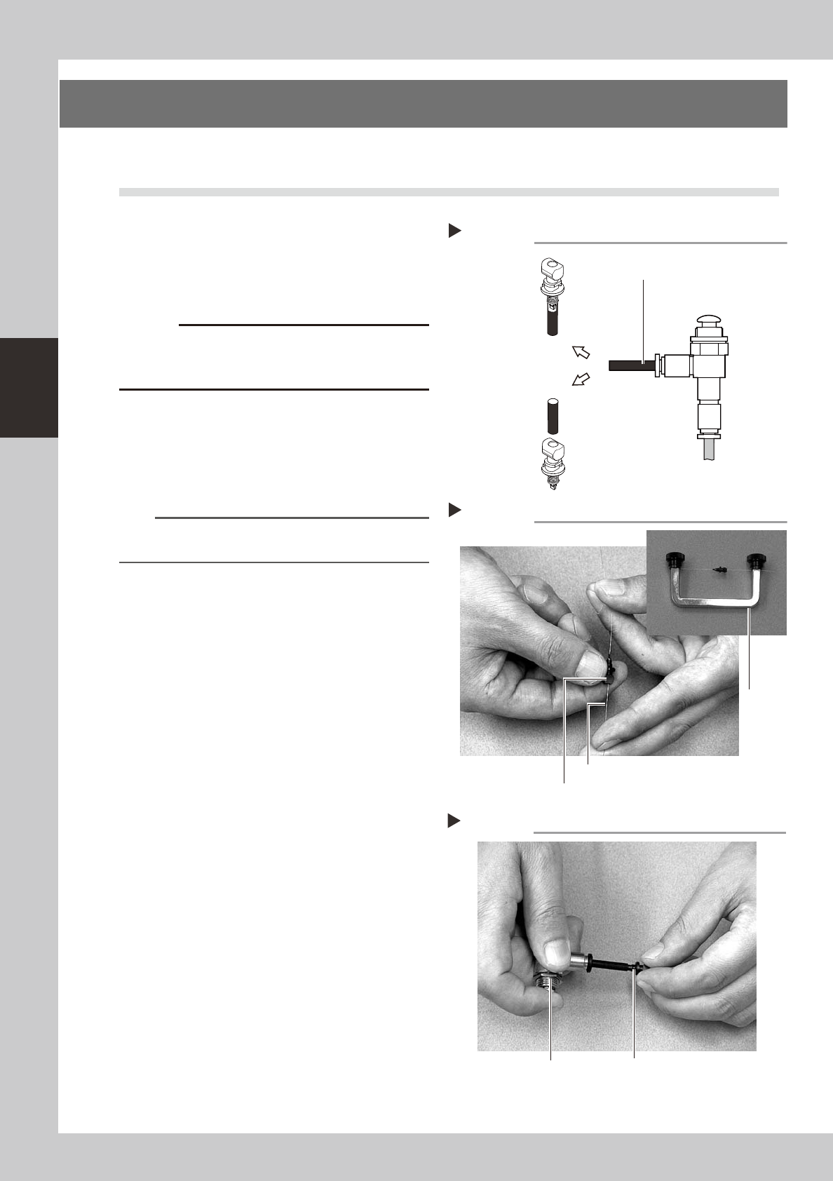
2.1 Cleaning the nozzle air path (monthly)
e
1
Remove the nozzle from the head.
Always first press the emergency stop button
and then remove the nozzle from the head.
The machine must be in emergency stop to
ensure safety during work.
c
When the machine is equipped with a nozzle station
nozzle station after cleaning.
2
Blow air through the nozzle.
Using an air blow gun, blow air through the
nozzle from the nozzle tip and then from the
other end.
53310-L6-00
n
NOTE
If there are dust deposits in the nozzle, perform steps 3
and 4.
3
Clean the nozzle hole.
Pass the nozzle cleaning wire through the
nozzle hole and clean the nozzle hole. While
holding both ends of the wire with fingers as
shown or using a custom handle (option),
gently move the nozzle back and forth.
53311-L6-00
4
Blow air onto the nozzle tip again.
After removing the cleaning wire, blow air
through the nozzle with the air blow gun, just
as in step 2.
53312-L6-00
Followingthenozzlecleaningabove,checkand
cleanthespring-actionparts.(See1.1.1,"Checking
andcleaningthespring-actionparts"described
earlierinthischapter.)
Air blow
Step 2
Air tube (black)
Air blow gun
(option)
Air tube (orange) connected to
air supply port
Insert the
nozzle tip into
the air tube and
blow air.
Blow air from the
nozzle attachment
side.
Cleaning a nozzle
Step 3
Custom
handle
(option)
Nozzle
Nozzle cleaning wire
Air blow
Step 4
NozzleAir blow gun (option)