YS12P_YS12F_YG12F_Mainte_E.pdf - 第59页
3-7 3 Periodic maintenance items 2.2 Inspecting each axis (monthly) AgreasespatteringpreventioncoverisattachedtotheX-axisandY-axis.Beforestartingtheinspectionwork, detachthisgreasespatteringpreventio…
3-6
3
Periodic maintenance items
2. Monthly or bimonthly inspection
This section mainly explains the cleaning and lubrication procedures after inspection.
2.1 Cleaning the nozzle air path (monthly)
e
1
Remove the nozzle from the head.
Always first press the emergency stop button
and then remove the nozzle from the head.
The machine must be in emergency stop to
ensure safety during work.
c
When the machine is equipped with a nozzle station
nozzle station after cleaning.
2
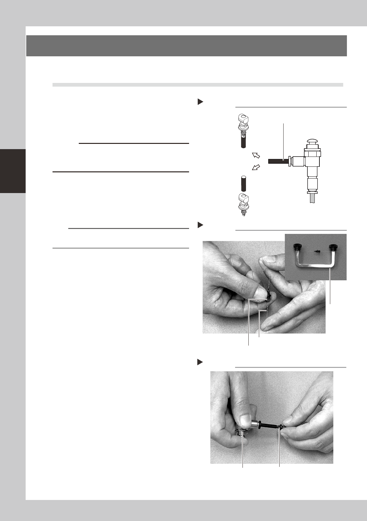
Blow air through the nozzle.
Using an air blow gun, blow air through the
nozzle from the nozzle tip and then from the
other end.
53310-L6-00
n
NOTE
If there are dust deposits in the nozzle, perform steps 3
and 4.
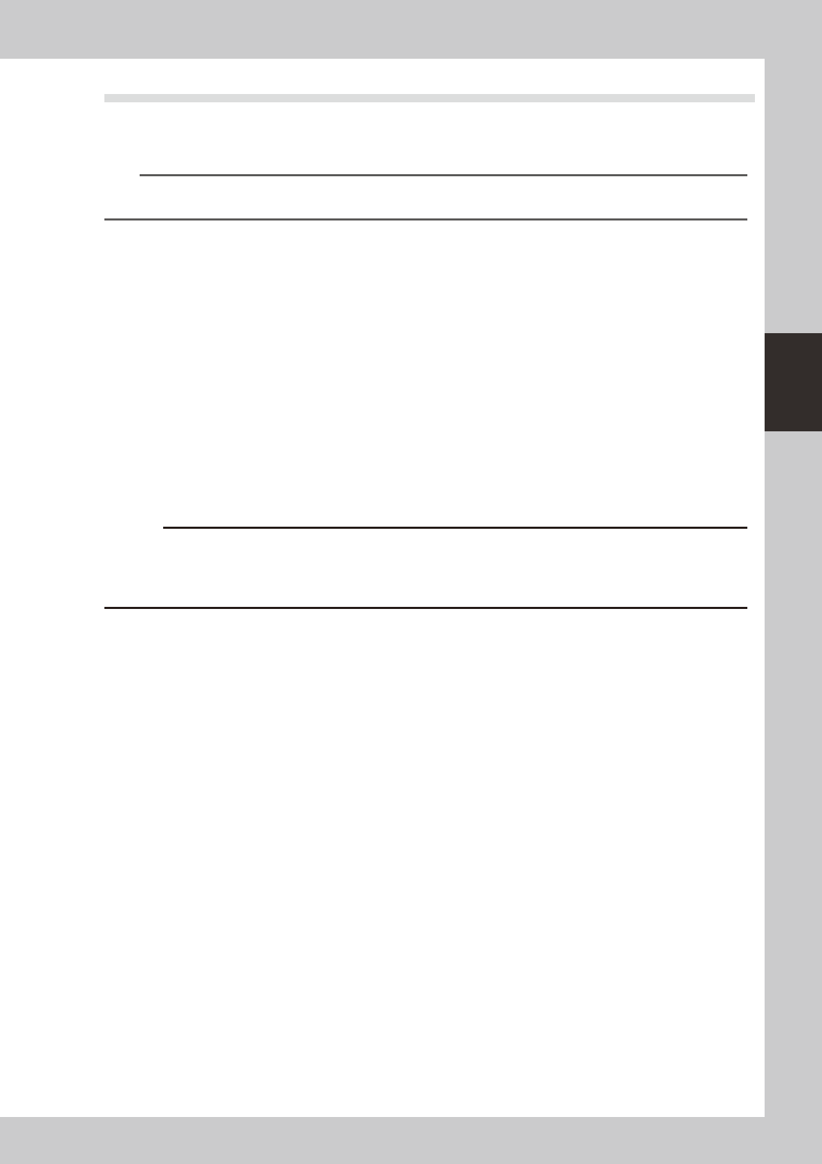
3
Clean the nozzle hole.
Pass the nozzle cleaning wire through the
nozzle hole and clean the nozzle hole. While
holding both ends of the wire with fingers as
shown or using a custom handle (option),
gently move the nozzle back and forth.
53311-L6-00
4
Blow air onto the nozzle tip again.
After removing the cleaning wire, blow air
through the nozzle with the air blow gun, just
as in step 2.
53312-L6-00
Followingthenozzlecleaningabove,checkand
cleanthespring-actionparts.(See1.1.1,"Checking
andcleaningthespring-actionparts"described
earlierinthischapter.)
Air blow
Step 2
Air tube (black)
Air blow gun
(option)
Air tube (orange) connected to
air supply port
Insert the
nozzle tip into
the air tube and
blow air.
Blow air from the
nozzle attachment
side.
Cleaning a nozzle
Step 3
Custom
handle
(option)
Nozzle
Nozzle cleaning wire
Air blow
Step 4
NozzleAir blow gun (option)
3-7
3
Periodic maintenance items
2.2 Inspecting each axis (monthly)
AgreasespatteringpreventioncoverisattachedtotheX-axisandY-axis.Beforestartingtheinspectionwork,
detachthisgreasespatteringpreventioncoverreferringto“Detachinggreasespatteringpreventioncover”
describedlateron.
TIP
For instructions on how to detach or attach the grease spattering prevention covers, refer to sections 2.3.1 and 2.3.2
described later on.
Checkpoints
1. Any foreign matter adhering to the ball screws and linear guides?
CheckifanyfallenchipshaveadheredtotheXandYaxisballscrewsand/orX,YandWaxislinearguides.
2. Do the ball screws and linear guides have the correct amount of grease?
Checkifgreasehasflowedofforsplatteredintheairfailingtoadhere.Alsocheckifgreasehasdiscoloredorhardened.
3. Any abnormal sounds from the ball screws?
Presstheemergencystopbutton.ThencheckforanyabnormalsoundswhilepressingtheX-axisorY-axisbyhand.
Countermeasures
1.Ballscrewsandlinearguidesmaybedamagedwhenchipsandothermaterialbiteintothem.Ifchipsareadhering,
wipethemoffalongwiththegreaseorremovewithtweezers,etc.
2.Applygreasewhilereferring“Cleaningandlubrication”describedlateron.
3.ConsultyourYAMAHAsalesofficeorrepresentativewhenabnormalsoundsoccurevenaftertryingthe
countermeasuresintheabovesteps1and2.
c
its contents.
3-8
3
Periodic maintenance items
2.3 Cleaning and greasing the X, Y and W axes (bimonthly)
TocleanandgreasetheballscrewsandlinearguidesoftheX,YandWaxes,followthestepsbelow.Prepare
agreasegunandspecifiedgrease(NSL).
c
c
2.3.1 Cleaning and greasing the X, Y and W axis ball screws
e
1
Press the emergency stop button.
The machine must be in emergency stop to
ensure safety during work.
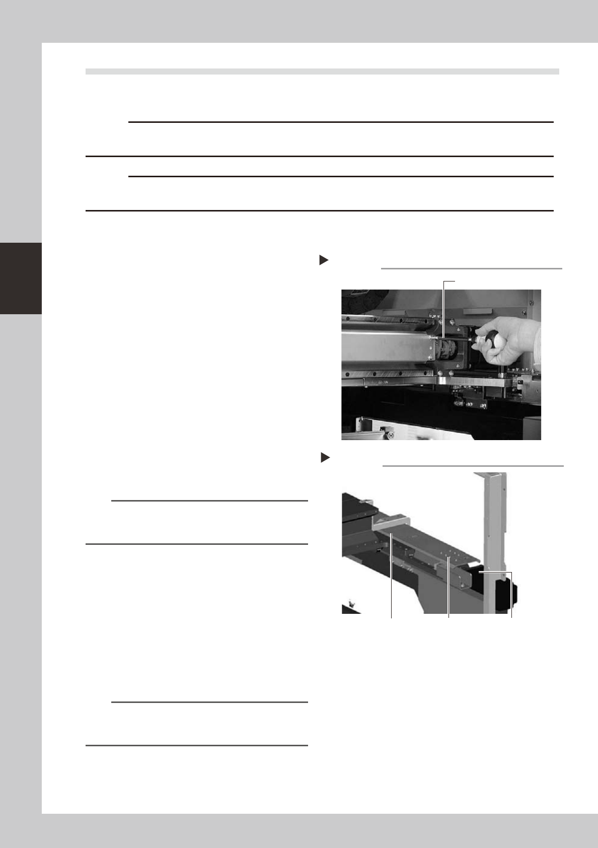
2
Remove the ball screw covers.
Remove the X-axis and Y-axis ball screw
covers used for preventing grease
spattering.
X-axis
1. Use a Phillips screwdriver to remove the
screws securing the left side of the
grease spattering prevention cover.
2. Move the head all the way to the left
side and remove the screws securing the
right side of the grease spattering
prevention cover.
3. Remove the grease spattering prevention
cover by pulling it to the right.
53305-L6-00
TIP
When reattaching the X-axis grease spattering
prevention cover, use the reverse order of the above
procedure.
Y1 and Y2 axes
1. Use the hex wrench to remove the bolts
securing the rear side of the grease
spattering prevention cover.
2. Move the head all the way to the rear
side and remove the bolts securing the
front side of the grease spattering
prevention cover.
3. Remove the grease spattering prevention
cover by pulling it to the front.
53306-L6-00
TIP
When reattaching the Y-axis grease spattering
prevention covers, use the reverse order of the above
procedure.
Removing the X-axis grease spattering prevention cover
Step 2
Phillips screwdriver
Y-axis ball screw cover
Step 2
Y-axis ball screw
cover mounting bolt
Y-axis motor
Removing the Y-axis grease spattering prevention cover