YS12P_YS12F_YG12F_Mainte_E.pdf - 第98页
A-1 Appendix 1. Specifications 1.1 Air regulator unit Theairregulatorforcontrollingtheairpressuretothepneumaticunitsofthemachineislocatedbehindthe frontlowerleftpanel.Adigitalpressuregaugeispr…

A-1
Appendix
1. Specifications
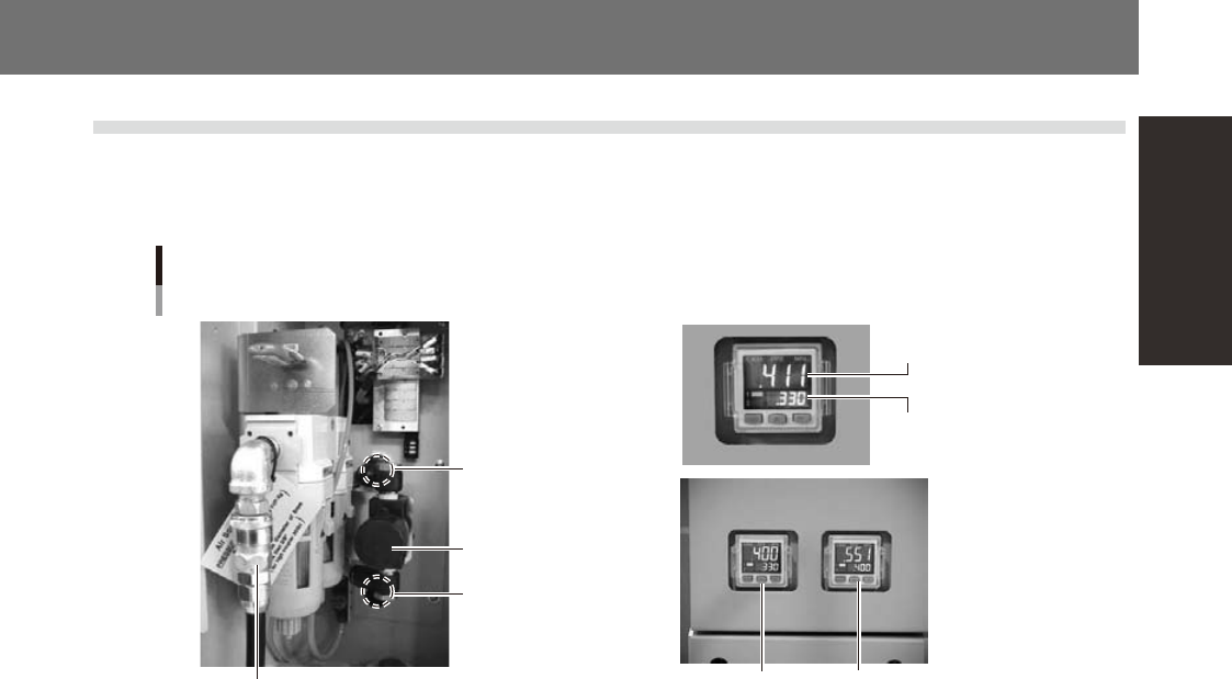
1.1 Air regulator unit
Theairregulatorforcontrollingtheairpressuretothepneumaticunitsofthemachineislocatedbehindthe
frontlowerleftpanel.Adigitalpressuregaugeisprovidedonthefrontleftofthemachine.Theairpressure
mustbesettotheoptimumlevel.
Air pressure setting
for machine
YS12P
YS12F
YG12F
Air pressure regulator and pressure gauge
Source air connector
Air pressure regulator
(For machine)
Air pressure
regulator
(For YG12F head
assembly)
For head assembly
setup
For machine setup
Air supply/shutoff
switch (valve)
Pressure-drop
detection level
53427-M7-00
n
Supply air pressure
Thisisthepressureofthesourceairsuppliedtothemachine.Beforesettingtheairpressurewiththeairregulator,make
surethatthissupplyairpressureisinthefollowingoptimalrange.
YS12P,YS12F:0.45MPato0.70MPa
YG12F:0.60MPato0.70MPa
n
Digital pressure gauge
Showsthesupplyairpressure(upperreading)andpressure-dropdetectionlevel(lowerreading).Anormalpressurevalue
isshowningreen,andapressurevaluelowerthanthepressure-dropdetectionlevelisshowninred.
n
Air pressure setting and pressure-drop detection level
• YS12P, YS12F
Airpressuresettingformachine(upperreading):0.40MPa
Pressure-dropdetectionlevel(lowerreading) :0.33MPa
• YG12F
Airpressuresettingformachine(rightupperreading) :0.55MPa
Pressure-dropdetectionlevel(rightlowerreading) :0.40MPa
Headsetuppressure(leftupperreading) :0.40MPato0.41MPa
Pressure-dropdetectionlevel(leftlowerreading) :0.33MPa
n
Air supply/shutoff switch (valve)
Turningthisswitchtotherightshutsoffairsupplyandexhaustsairthatremainsinsidethemachine.
n
Source air connector
Prepareanairhosewithaninnerdiameterofatleast8mmhavinga40SHsocket(NittoKoki,orequivalent),andconnect
ittothisconnector.Usedry,cleanairpassedthroughanairfilter.
A-2
Appendix
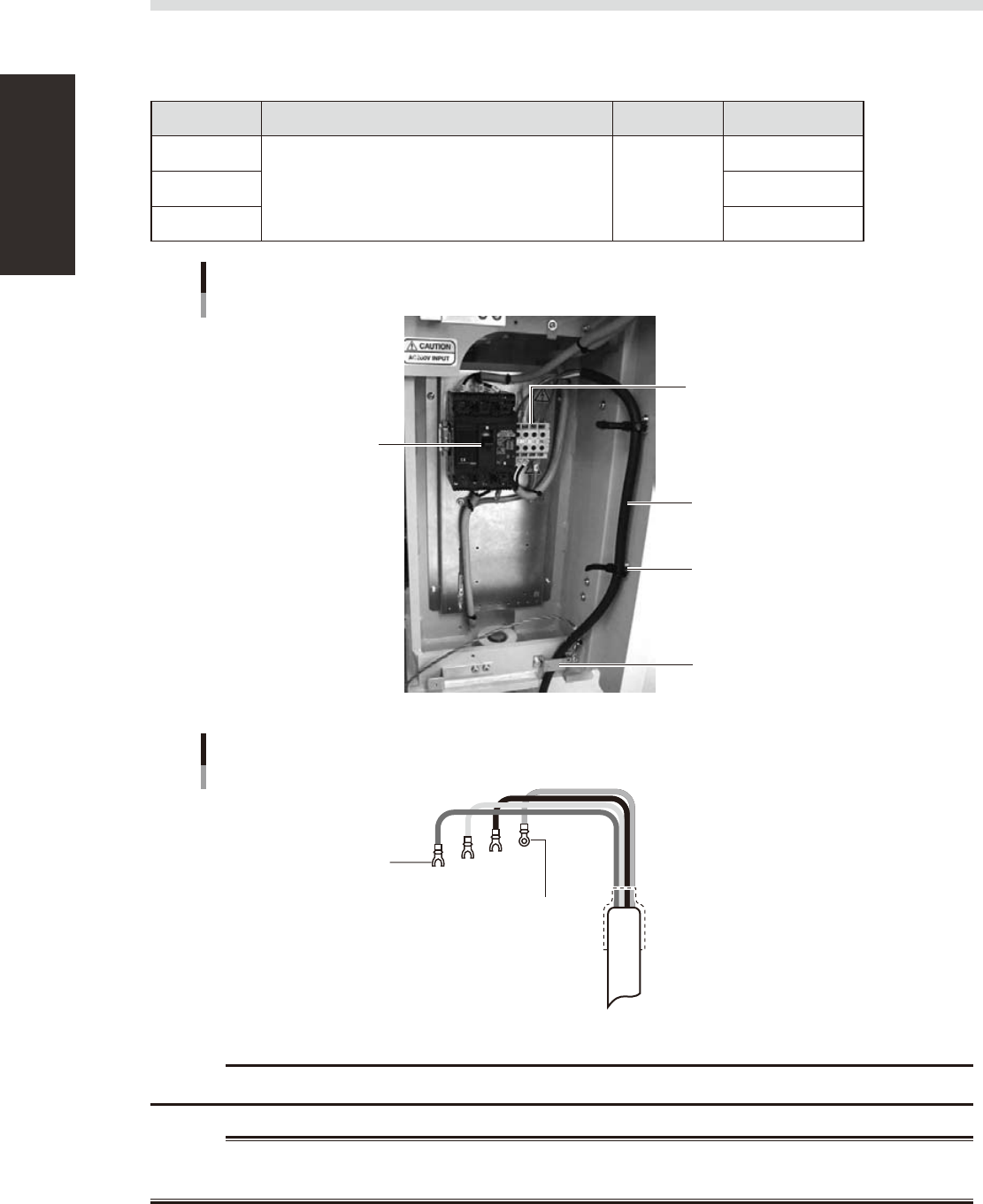
1.2 Power connection terminals
Thepowerconnectionterminalsarelocatedinsidethelowerrightpanelonthefrontofthemachine.Connect
thepowercableleadsasshownbelowtotheL1,L2,L3andgroundterminal(PE)onthepowerterminalblock.
n
Power supply specifications
Model name Power Frequency Power capacity
YS12P
3-phase AC 200/208/220/240/380/400/416V (±10%) 50/60Hz
3.6KVA
YS12F 4.3KVA
YG12F 4.3KVA
Power connection terminals
Main breaker
Power input terminals
(L1, L2, L3) and ground terminal
Power cable
Secure the clamps at two
positions
Wire through this clamp plate
53433-M7-00
L1
L2
L3
PE
L=100mm
Power cable example
Fork-tongue crimp terminal
Ring-tongue crimp
terminal
53434-M7-00
c
Use a power cable whose conductor cross-section area is greater than 3.5mm
2
.
w
WARNING