YS12P_YS12F_YG12F_Mainte_E.pdf - 第70页
3-18 3 Periodic maintenance items 3.1.2 Checking the blow valve operation (each head) Checktheblowlevelofeachejectoroftheejectorunittoseeifitisworkingcorrectly. 1 Check that the blow air is being exhaust…
3-17
3
Periodic maintenance items
3.1.1 Checking the ejector vacuum pressure
Checkthevacuumlevelofeachejectoroftheejectorunittoseeifitisworkingcorrectly.
e
1
Press the emergency stop button.
The machine should be in emergency stop
to ensure safety during work.
2
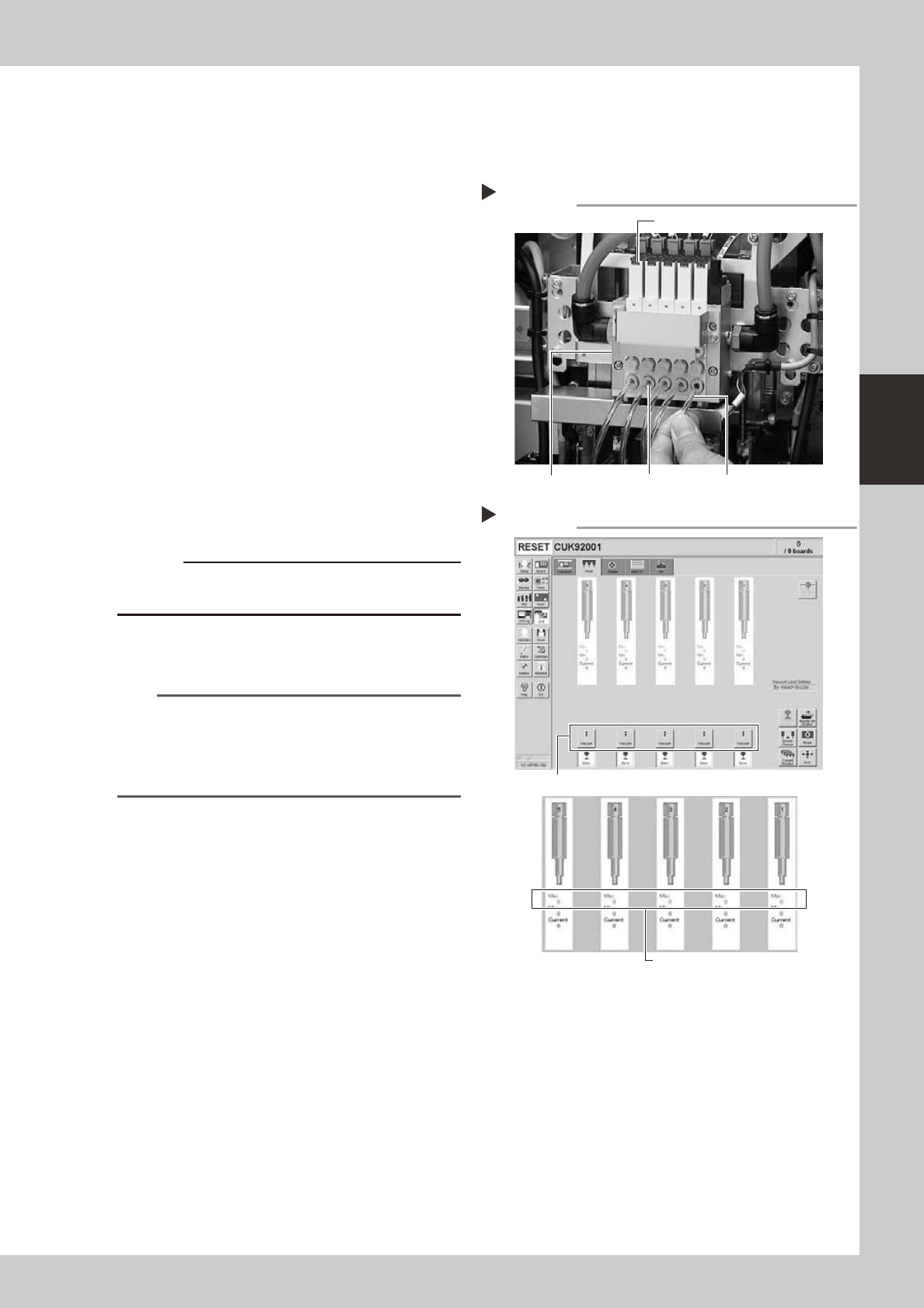
Disconnect the air hose from the
air joint under each ejector.
Disconnect all air hoses from the air joints (air
couplings).
53333-L6-00
3
Check the ejector vacuum level.
1. Open the [Unit]-[Head] tab.
2. Press the [Vacuum] button while blocking
each air joint with your finger.
3. Make a note of the "Max" reading of
each head while the air joint is blocked,
and check that the reading is higher
than the criterion value below.
Make the same check for all heads.
54305-L6-10
c
to wear safety goggles.
n
Criterion of ejector vacuum level
Whenairjointisblocked:190ormore
TIP
If the vacuum level of any head does not reach the
criterion value, then check the air path in the head
(interior of the spline shaft or air hose between the
ejector and spline shaft). Clean or replace it if
necessary.
Disconnecting the air hoses
Step 2
Transparent air hoseAir jointEjector unit
Ejector
Checking the vacuum levels
Step 3
Press the [Vacuum] button for each head.
Check "Max" vacuum levels
(with air joint blocked).
3-18
3
Periodic maintenance items
3.1.2 Checking the blow valve operation (each head)
Checktheblowlevelofeachejectoroftheejectorunittoseeifitisworkingcorrectly.
1
Check that the blow air is being
exhausted correctly.
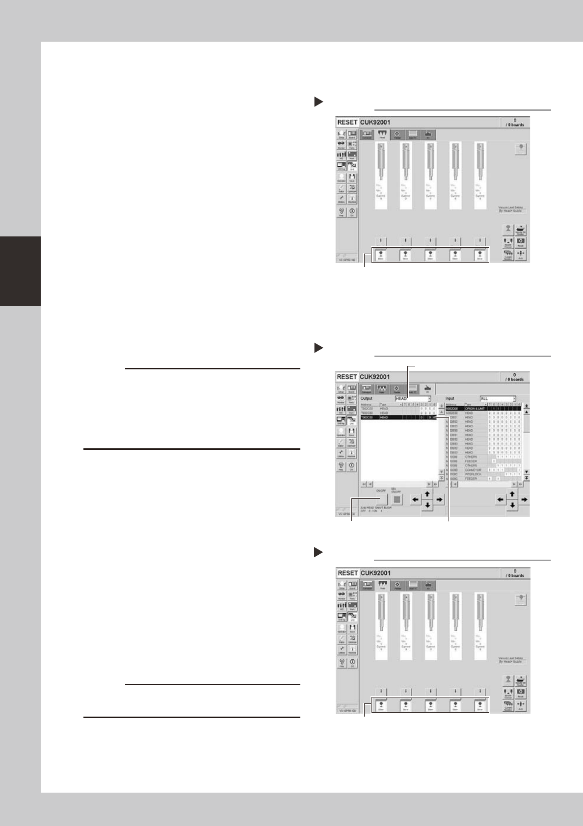
To check if the blow air is being uniformly
exhausted from each air joint on the lower
part of the ejector unit, open the [Unit]-
[Head] tab and press the [Blow] button for
each head.
54307-L6-10
3.1.3 Checking the cleaning blow valve operation (for all heads)
Checkthatthecleaningblowfunctionforthesplineshaftsisworkingcorrectly.
1
Remove the nozzles from all heads.
c
A strong air flow is exhausted during the cleaning blow.
Always remove all nozzles attached to the heads before
starting the cleaning blow. Starting the cleaning blow
while the nozzles are still attached may blow the
nozzles away from the heads causing the nozzles to
break or become lost.
2
Operate the cleaning blow valves.
1. Open the [Unit]-[I/O] tab.
2. Select [Head] from the Output dropdown
list and select the address for the head
shaft blow (T003C000).
3. Press the [ON/OFF] button
to operate the
cleaning valves of all heads.
54313-M7-00
3
Check the exhaust blow air of each
head.
Open the [Unit]-[Head] tab. Press the [Blow]
button of each head to check the exhaust
blow air from each head.
54308-L6-10
4
Turn OFF the cleaning blow valves.
c
The cleaning air blow or exhaust air blow might strike
Checking the blow air exhaust
Press the [Blow] button for each head.
Step 1
Step 2
Operating the cleaning blow valves.
Press the [ON/OFF] button. Select an address.
Select a head.
Checking the blow air
Step 3
Press the [Blow] button for each head.
3-19
3
Periodic maintenance items
3.2 Cleaning and lubricating the inside of the spline shaft
Dustorgrimemayadheretotheairpathofsplineshaftsandcausecomponentpickupormountingerrors.
Althoughdependingontheairsupplyconditionandoperatingtime,theinsideofeachsplineshaftshouldbe
cleanedonceevery3months.
c
3.2.1 Cleaning the inside of the spline shaft
e
1
Press the emergency stop button.
The machine should be in emergency stop
to ensure safety during work.
2
Move the head to a convenient
position for maintenance work.
n
NOTE
Move the scan camera to the right or left away from
the head assembly so that the scan camera will not get
dirty.
3
Remove the nozzles from all heads.
Remove all nozzles by hand.
TIP
When the machine is equipped with a nozzle station
(option), place the nozzles removed from the heads
back to the nozzle station.
4
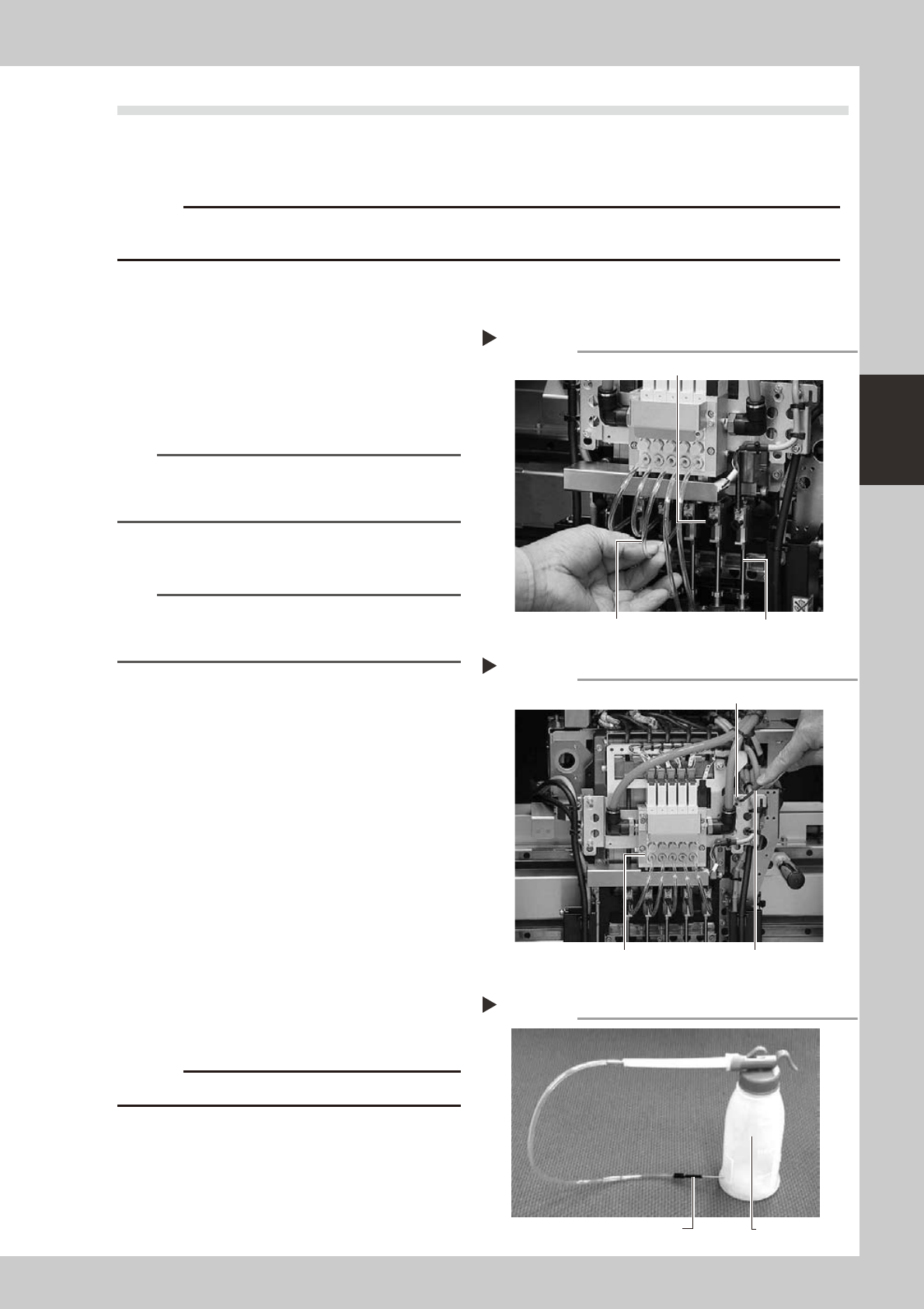
Disconnect the air hose from each
spline shaft.
Disconnect the air hose inserted into the
upper part of each spline shaft.
53318-L6-00
5
Remove the ejector unit stay.
Use the hex wrench or T-handle hex wrench
to remove the four bolts that secure the
ejector unit stay.
53309-L6-00
6
Prepare the cleaning kit (KHN-
M8860-00X).
1. Pour IPA (isopropyl alcohol) into the
container of the cleaning kit.
2. Place a shop cloth or rag under the
spline shaft to be cleaned.
53319-L6-00
c
Never use solvent other than IPA (isopropyl alcohol).
Disconnecting the air hoses
Step 4
Air hose
Spline shaft air joint
Spline shaft
Removing the ejector unit stay
Step 5
Hex wrench or T-handle hex wrench
Ejector unit stay
Ejector valve
Cleaning kit
Step 6
Pump (IPA container)
Nozzle