YS12P_YS12F_YG12F_Mainte_E.pdf - 第84页
3-32 3 Periodic maintenance items 4.5 Inspecting and cleaning the controller filter (1 year) Afanisinstalledonthelowerpartofthecontrollertocoolthecircuitboardsinsidethecontroller.Turningon themainp…
3-31
3
Periodic maintenance items
4.4 Checking the nozzle station sensor condition (1 year) … option
Whenthemachineisequippedwithanozzlestation(option),checkthenozzlestationsensorstoseeifthey
areworkingcorrectly.
c
operation may be interrupted due to a nozzle detection error.
e
1
Press the emergency stop button.
The machine should be in emergency stop
to ensure safety during work.
2
Open the nozzle station shutter.
1. Open the [Unit]-[Head] tab.
2. Press the [Nozzle Stn Shutter] button to
open the nozzle station shutter.
54303-L6-10
3
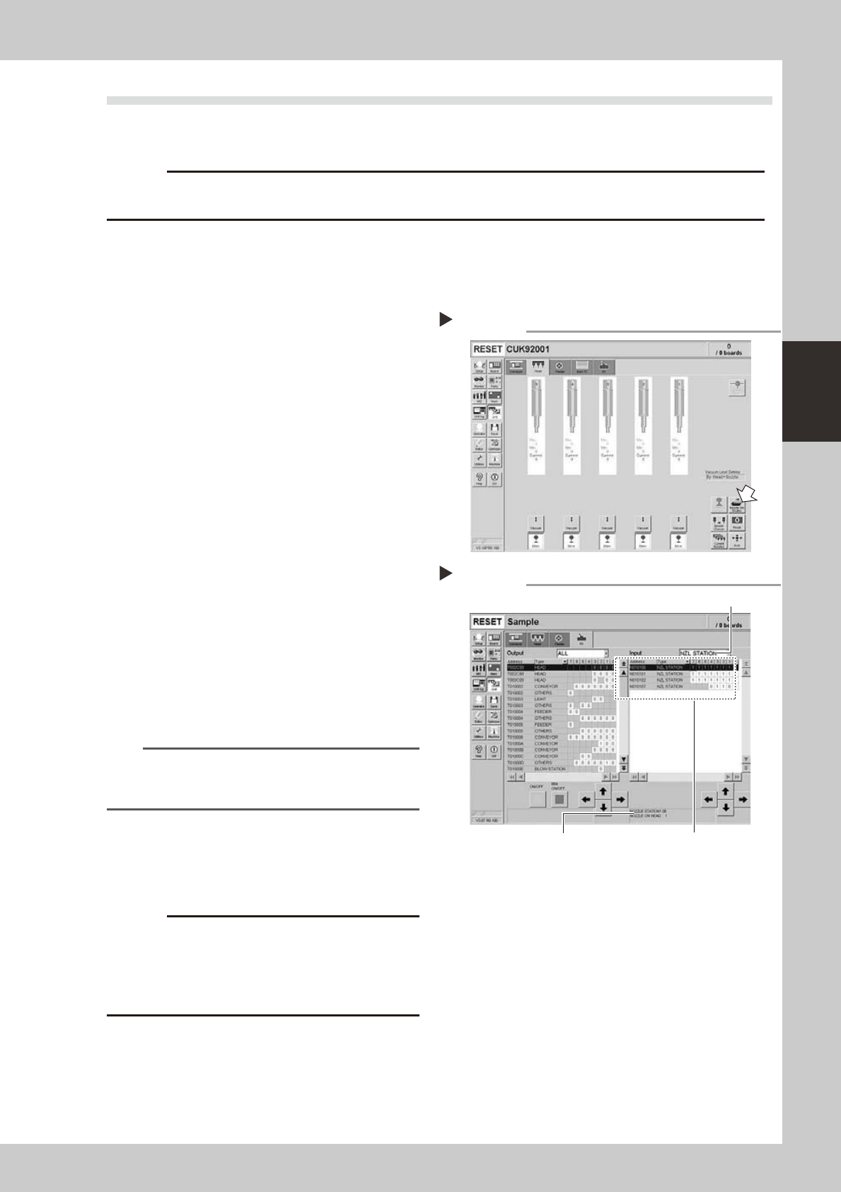
Check the detection status of the
nozzle station sensors.
Check to see if the nozzle station sensors
detect the presence or absence of nozzles.
1. Open the [Unit]-[I/O] tab.
2. From the "Input" drop-down list, select
"NZL STATION".
3. While extracting a nozzle from the nozzle
station and returning it to the same
position, check whether the
corresponding sensor detects the nozzle
correctly.
The detection status on the screen should
read "1" when the nozzle is extracted
from the nozzle station, and should read
"0" when the nozzle is in the nozzle
station.
54306-L6-10
TIP
The nozzle station position No. where a nozzle was
extracted or inserted is displayed on the lower part of
the "Input" status screen.
4
Close the nozzle station shutter.
On the [Unit]-[Head] tab, press the [Nozzle
Stn Shutter] button to close the nozzle station
shutter.
c
If the detection status of a nozzle station sensor is
cleaning of the nozzle station sensors by the user will
void the warranty.
Opening the shutter
Step 2
Checking the nozzle detection status
Step 3
Select "NZL STATION".
Nozzle station position No. is
displayed here.
Shows the presence or absence
of nozzles detected by sensors.
3-32
3
Periodic maintenance items
4.5 Inspecting and cleaning the controller filter (1 year)
Afanisinstalledonthelowerpartofthecontrollertocoolthecircuitboardsinsidethecontroller.Turningon
themainpowerstartsacontinualsupplyofair.Thefilterremovesdustfromtheairtakeninthroughthefan.
Accumulateddustmaycausefaultyoperation,socleanthefilterperiodically.
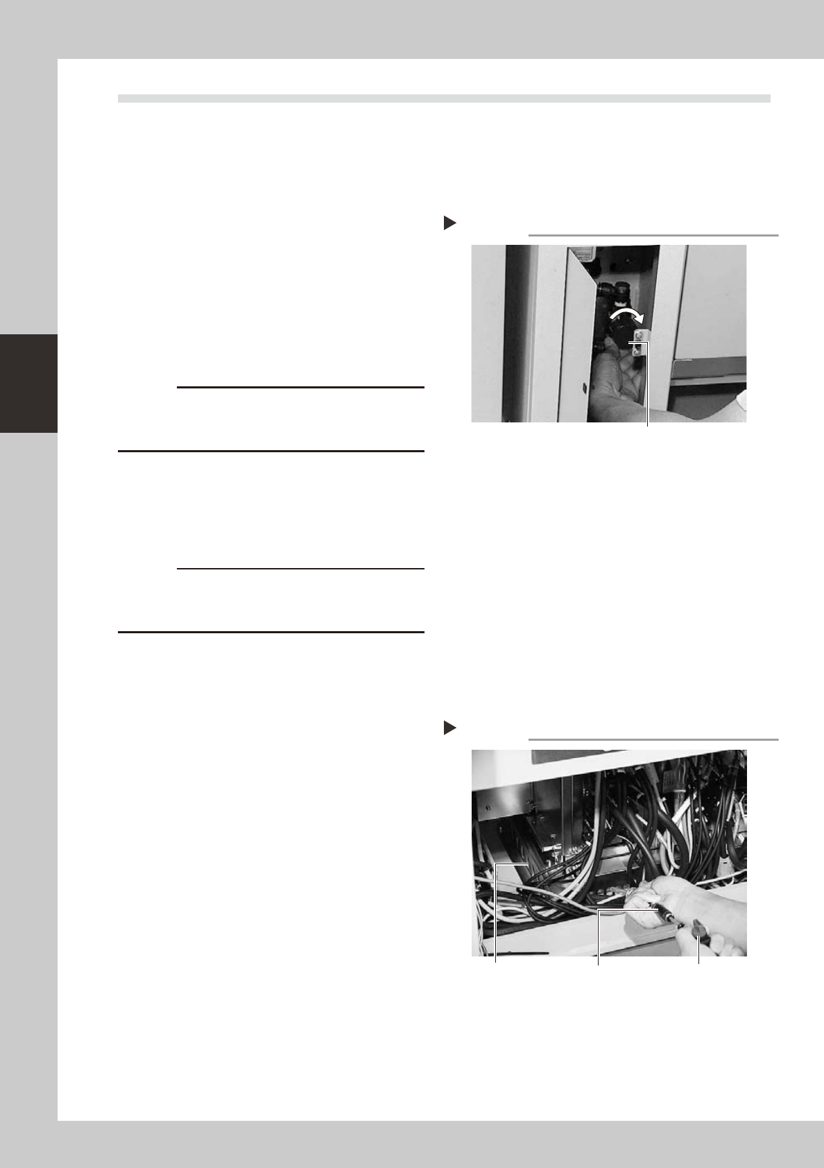
1
Turn off the air supply and the
power to the machine.
Quit the software and turn off the machine
power switch. Then turn the air supply/shutoff
valve inside the machine lower left panel to
the right.
53346-L2-00
2
Open the air release valve inside
the tape cutter.
Discharge any remaining air that is
accumulated inside the tape cutter.
c
tape cutter must be discharged to free the tape cutter
blade.
3
Remove the front tape cutter ducts.
Use a Phillips screwdriver to remove the
screws securing the left and right tape
cutter ducts, and remove the ducts.
(Remove a total of 6 screws.)
c
Removing the tape cutter ducts exposes the tape cutter
blade. Coming in contact with the blade may cause
4
Remove the front lower panel to
access to the controller.
Remove the front panel under the machine
front base, where the controller is installed.
5
Prepare the vacuum ASSY.
Connect the vacuum assembly (KHY-M88V0-
A0X) to the air connector of an upstream or
downstream machine.
53350-L2-00
6
Start the cleaning work.
1. Turn the air switch on the vacuum ASSY
to the ON position.
2. Pass the top end through the slit of the
filter cover. The cleaning portions are
located on the front, left, and right sides.
7
Close the air release valve inside
the tape cutter.
8
Turn on the machine power and
start the air supply.
Turn on the machine power switch and also
start the air supply by turning the air supply/
shutoff valve inside the machine lower left
panel to the left.
Turning off the air supply
Step 1
Air supply/shutoff valve
Cleaning work
Step 6
Vacuum ASSY
Filter cover
Air switch
3-33
3
Periodic maintenance items
4.6
Cleaning the multi-view camera lens and lighting unit (1 year) …. option
Themulti-viewcameralensandlightingunitareenclosedinsidetheprotectiveglass.Tocleanthelensand
lightingunit,removetheprotectiveglass.Iftheprotectiveglassisdirty,cleanit(seesection3,"Cleaningthe
cameraprotectiveglass",inChapter2).
1
Turn off the power to the machine.
Quit the software and turn off the machine
power switch.
2
Remove the upper cover of the
multi-view camera.
Use a hex wrench to remove the two
thin-head screws on the upper cover of the
multi-view camera. Then carefully lift the
multi-view camera cover straight up and
remove it.
53341-L2-00
3
Remove the transparent protective
glass.
Use a Phillips screwdriver to remove the
screws securing the glass mount plate.
53342-L2-00
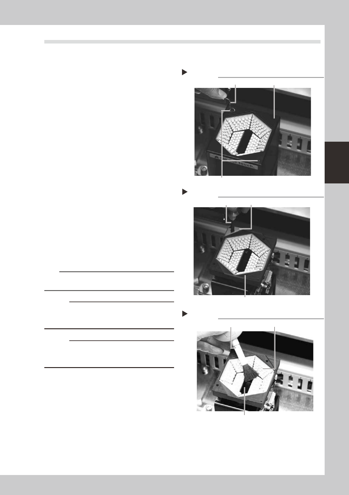
4
Clean the lighting unit.
1. Many LEDs are mounted on the lighting
board. Use a lens brush to clean the LEDs.
2. A half mirror is located in the center
opening of the lighting unit. Clean the
half mirror using a lens brush, lint-free
cotton swab, lens cleaner, etc.
53343-L2-00
TIP
Lens brush, lint-free cotton swab, and lens cleaner are
available as options.
c
or may cause short-circuits.
c
The half mirror is very thin with a thickness of 1.0mm.
Even a small shock can cause cracks. Use extreme
caution when cleaning the half mirror.
5
Reinstall the lighting unit protective
glass.
Reinstall the lighting unit protective glass
and multi-view camera cover at their
original positions.
Removing the multi-view camera cover
Step 2
Hex wrench
Thin-head screw
Multi-view camera cover
Removing the protective glass
Step 3
Phillips screwdriver
Protective glass
Glass mount plate
Cleaning the multi-view camera lighting unit
Step 4
Lens brush
Half mirror glass
LED