YS12P_YS12F_YG12F_Mainte_E.pdf - 第74页
3-22 3 Periodic maintenance items 3.2.2 Checking the negative pressure Aftercleaningthesplineshafts,checkthenegativepressure(vacuumlevel)generatedineachhead. 1 After assembly , check the vacuum lev els. 1. …
3-21
3
Periodic maintenance items
0
Blow air into the spline air path.
1. Prepare an air blow gun (available as
option) and connect it to an air
connector on a nearby machine. Then
insert the air blow gun nozzle into the air
joint of the spline shaft.
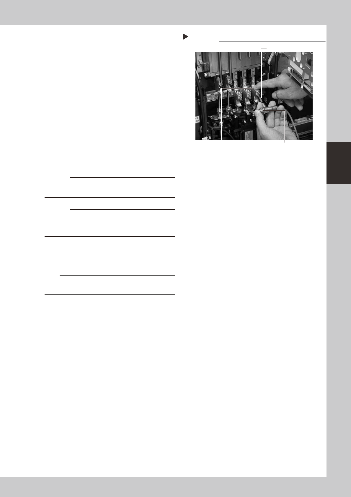
2. Place a shop cloth under the lower end
of the spline shaft, and blow air through
the spline shaft while blocking the
cleaning hole with your finger.
3. Repeat the above procedure (steps 9
and 10) until the IPA flowing out from the
spline shaft becomes clean. Make sure
that after blowing air, smear no longer
appears on the shop cloth placed under
the lower end of the spline shaft, and
then reattach the cap bolt.
53334-L6-00
c
to wear safety goggles.
c
not to drop it.
q
Reattach the spring to suspend the
spline shaft.
Hook the spring to the hook pin by hand.
n
NOTE
Clean the inside of all spline shafts using the same
procedure in steps 7 to 11.
w
Repeat the cleaning procedure.
Repeat steps 7 to 11 to clean the inside of
the spline shafts of all heads.
e
Reinstall the ejector unit stay back
to its original position.
Tighten the four bolts to secure the ejector
unit stay, using the hex wrench or T-handle
hex.
r
Reconnect the air hoses back to
their original positions.
Air blow into spline shaft
Step 10
Nozzle of air blow gun
Air blow switchBlock the cleaning hole with your finger.
3-22
3
Periodic maintenance items
3.2.2 Checking the negative pressure
Aftercleaningthesplineshafts,checkthenegativepressure(vacuumlevel)generatedineachhead.
1
After assembly, check the vacuum
levels.
1. Leave nozzles detached from the heads.
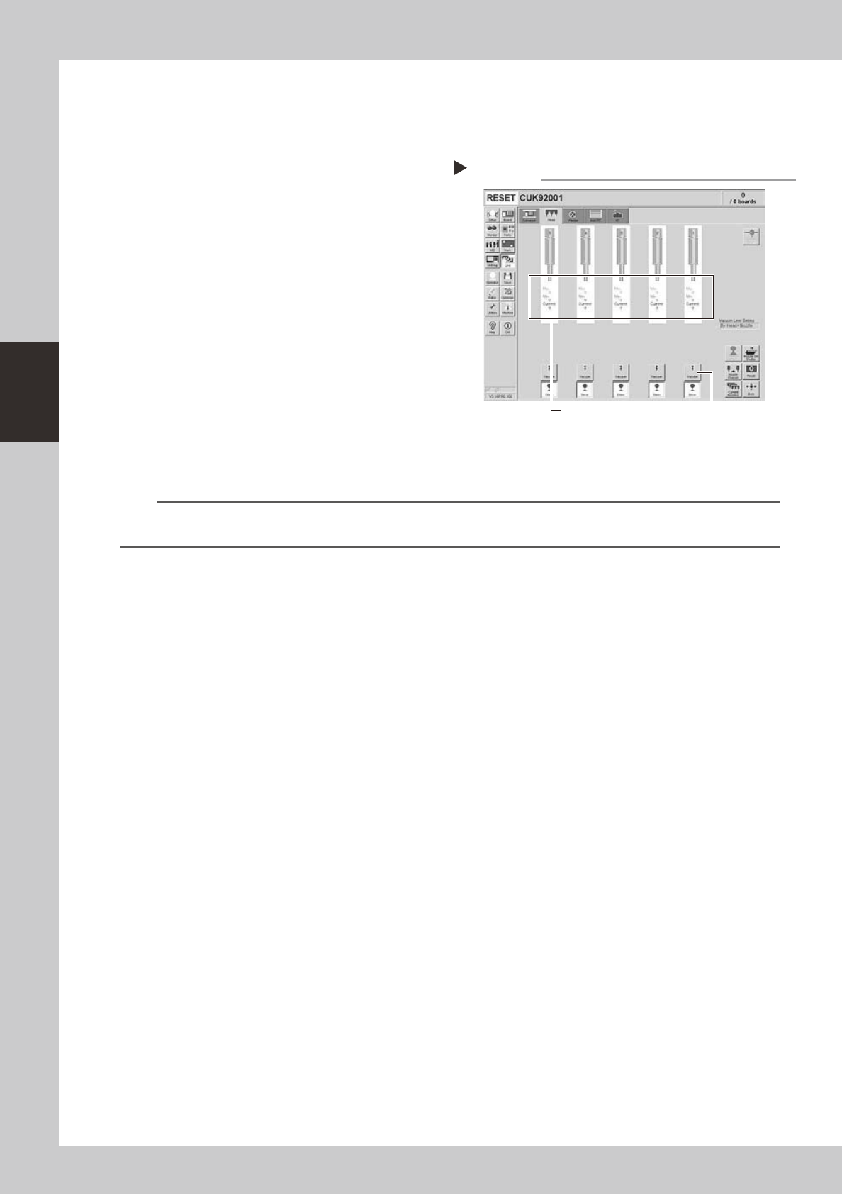
2. Open the [Unit]-[Head] tab screen and
press the [Vacuum] button to generate a
negative pressure. Read the "Max" values
shown on the screen and determine
whether the vacuum levels are
appropriate by referring to the criteria
below.
54311-L6-10
2
Reattach the nozzles.
Attach the nozzles by hand back to the
heads.
n
Vacuum level criteria in spline air path
Whennozzleisopen :70orless
Whennozzleissealed:190ormore
n
NOTE
The vacuum level in the spline shaft air path might sometimes differ slightly depending on the air source and operating
conditions. Use the above criteria for reference during maintenance.
Checking the vacuum level
Step 1
[Vacuum] buttonRead "Max" values.
3-23
3
Periodic maintenance items
3.3
Checking the spline shaft movement and lubricating the slide section
Aftercleaningthesplineshafts,checkthesplineshaftmovementandlubricatetheslidesection.
c
1
Turn off the machine power switch.
Quit the software and turn off the machine
power switch.
2
Move each spline shaft by hand to
check for abnormal movement.
Move each spline shaft up and down by
hand and make sure that all spline shafts
move smoothly without hanging up and
unusual noise.
c
If the machine is operated while movement of any
assistance.
3
Clean the outside of each spline
shaft.
Use a lint-free cleaning wiper or cotton swab
to wipe the outside of each spline shaft.
4
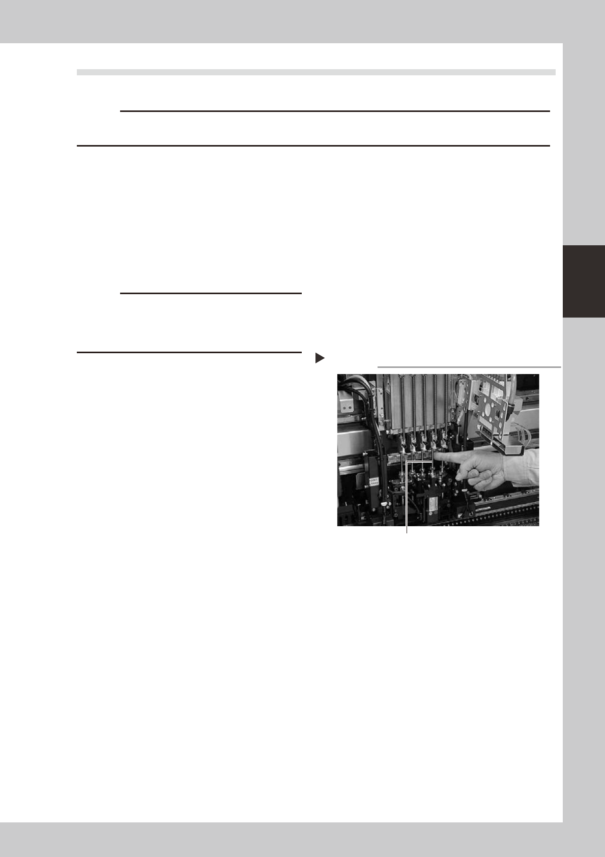
Apply grease to the outside of each
spline shaft.
Apply a thin, uniform coat of grease by hand
to the outside of each spline shaft.
53335-L6-00
5
Wipe away excess grease.
Move each spline shaft by hand several
times and wipe away excess grease.
Applying grease to spline shaft
Step 4
Z-axis spline shaft